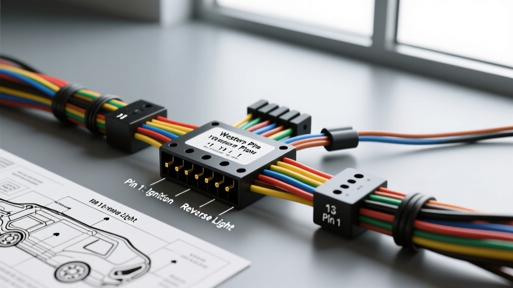
Western Plow Electrical Architecture Overview
Western snow plows rely on two primary electrical architectures to manage hydraulic valve actuation, lighting, and controller communication: the legacy Standard Relay (SR) system and the modern Multiplex (UltraMount/UltraGuard) system. Understanding the exact Western plow wiring diagram for your specific connector configuration is critical for preventing voltage drop, solenoid coil burnout, and CAN-bus communication errors. Unlike generic automotive circuits, snow plow harnesses are subjected to extreme thermal cycling, high-amperage inductive loads, and severe environmental exposure. This technical specification reference details the precise pinouts, wire gauges, and routing requirements for Western 11-pin and 13-pin harness systems, ensuring reliable operation in sub-zero conditions.
11-Pin Standard Relay (SR) Harness Pinout Specification
The 11-pin circular connector is the industry standard for Western Standard Relay systems, commonly found on older UltraMount and Pro-Plus models. This harness carries discrete 12V DC signals from the in-cab controller and the vehicle's lighting circuit directly to the plow-side relay pack and hydraulic valves. The connector utilizes a weather-sealed thermoplastic housing with silicone radial seals to prevent moisture ingress.
| Pin | Function | Wire Color | AWG Size | Circuit Notes |
|---|---|---|---|---|
| 1 | System Ground | White | 12 AWG | Common ground for all valve coils and lighting. |
| 2 | Marker/Clearance | Brown | 14 AWG | Fused at 10A on the truck-side harness. |
| 3 | Left Turn/Brake | Yellow | 14 AWG | Intercepted from OEM trailer/taillight circuit. |
| 4 | Right Turn/Brake | Green | 14 AWG | Intercepted from OEM trailer/taillight circuit. |
| 5 | Headlight Low Beam | Red | 14 AWG | Triggered via Headlight Isolation Module (HIM). |
| 6 | Headlight High Beam | Blue | 14 AWG | Triggered via HIM; includes diode protection. |
| 7 | Motor Solenoid ON | Black/Orange | 12 AWG | Carries 15-20A to trigger the heavy-duty motor solenoid. |
| 8 | Lift Valve (S1) | Brown/White | 14 AWG | Actuates the lift/lower directional valve coil. |
| 9 | Drop Valve (S2) | Orange/Black | 14 AWG | Actuates the drop speed or float valve coil. |
| 10 | Left Angle (S3) | Green/White | 14 AWG | Actuates the left-angle hydraulic cartridge valve. |
| 11 | Right Angle (S4) | Purple/White | 14 AWG | Actuates the right-angle hydraulic cartridge valve. |
Technical Note: The hydraulic motor power does not pass through this 11-pin connector. Pin 7 merely provides the low-amperage trigger signal to the high-amperage solenoid coil located on the plow frame. According to the Western Technical Library, attempting to route motor current through the 11-pin harness will result in immediate connector meltdown and catastrophic harness failure.
13-Pin Multiplex UltraMount Harness Pinout
Newer Western Multiplex systems (such as those utilizing the UltraMount 2 or Fleet Flex architectures) consolidate wiring using a digital communication bus. The 13-pin connector replaces the discrete analog signals with a localized Controller Area Network (CAN-bus) and multiplexed power nodes, significantly reducing copper weight and minimizing voltage drop over long harness runs.
| Pin | Function | Wire Color | AWG Size | Circuit Notes |
|---|---|---|---|---|
| 1 | Battery Positive (Switched) | Red | 10 AWG | Powers the plow-side multiplex node module. |
| 2 | System Ground | Black | 10 AWG | Primary ground return for the multiplex node. |
| 3 | CAN-High (Data +) | Green | 18 AWG (Shielded) | Digital communication bus; requires 120-ohm termination. |
| 4 | CAN-Low (Data -) | Yellow | 18 AWG (Shielded) | Digital communication bus; twisted pair with Pin 3. |
| 5 | Marker/Clearance | Brown | 14 AWG | Multiplexed output to LED marker lamps. |
| 6 | Left Turn/Brake | Yellow | 14 AWG | Multiplexed output; PWM compatible. |
| 7 | Right Turn/Brake | Green | 14 AWG | Multiplexed output; PWM compatible. |
| 8 | Low Beam Trigger | White | 14 AWG | Signal from truck-side isolation module. |
| 9 | High Beam Trigger | Blue | 14 AWG | Signal from truck-side isolation module. |
| 10 | Ignition 12V Sense | Red/White | 14 AWG | Wakes the multiplex node; prevents battery drain. |
| 11 | Auxiliary Output 1 | Purple | 14 AWG | Reserved for work lights or defrosters. |
| 12 | Auxiliary Output 2 | Gray | 14 AWG | Reserved for future accessories. |
| 13 | Shield Drain Wire | Bare Copper | 18 AWG | Must be grounded at the truck node to prevent EMI. |
The 18 AWG shielded twisted pair (STP) used for Pins 3 and 4 is critical. Snow plow environments generate massive electromagnetic interference (EMI) from the hydraulic motor's inductive kickback and the vehicle's alternator. The SAE J1128 standard for low-tension primary cable dictates strict insulation requirements, but the shielding on the CAN-bus lines must be maintained continuously through the connector backshell to prevent data packet loss, which manifests as erratic joystick behavior or complete controller lockout.
High-Amperage Motor and Solenoid Routing Specifications
The hydraulic power unit (HPU) motor on a Western plow typically draws between 150A and 250A under peak load (e.g., when angling the blade against a heavy snowbank or lifting a fully loaded blade). This current requires dedicated, heavy-gauge cabling completely separate from the control harness.
Power Cable Specifications
- Wire Gauge: 2 AWG SAE J1128 stranded copper (minimum). For truck bed lengths exceeding 8 feet, upgrade to 1/0 AWG to mitigate voltage drop.
- Overcurrent Protection: 250A Megafuse or Class T fuse, mounted within 18 inches of the truck battery positive terminal.
- Solenoid Type: Trombetta or White-Rodgers 12V DC, 4-terminal intermittent duty solenoid (rated for 200A continuous / 800A inrush).
- Ground Return: 2 AWG cable from the motor case directly to the truck chassis or battery negative. Never rely on the hydraulic pivot pins or mounting brackets for the primary ground return.
Termination and Torque Specifications
Voltage drop at the lug terminations is the leading cause of slow plow performance and solenoid failure. All 2 AWG and 4 AWG cables must utilize closed-end, adhesive-lined heat-shrink ring terminals. The hardware torque specifications are critical for maintaining surface contact area:
- 1/4-inch Ring Terminal Hardware: 10 to 12 ft-lbs.
- 3/8-inch Ring Terminal Hardware: 20 to 25 ft-lbs.
- Motor Stud Nuts: 45 to 50 in-lbs (do not overtighten, as the motor casing threads are prone to stripping).
Headlight Isolation Module (HIM) Integration
Modern trucks utilize Pulse Width Modulation (PWM) and Body Control Modules (BCM) to manage exterior lighting. Connecting a plow harness directly to an OEM headlight circuit will often trigger a BCM 'bulb-out' fault, shutting down the circuit entirely. The Western Headlight Isolation Module (HIM) intercepts the OEM signals and powers the plow lights via a dedicated relay pack.
When wiring the HIM, you must identify whether the truck uses an HB4 (9006), H11, or H13 OEM connector. The Western adapter harness utilizes high-impedance sense wires (typically 18 AWG Green/White and Green/Black) that draw less than 5mA to detect the presence of the OEM headlight signal without loading the BCM. If the plow lights flicker or fail to switch between high and low beams, verify the HIM ground wire (14 AWG White) is secured to a clean, bare-metal chassis point with a star washer, torqued to 15 ft-lbs.
Diagnostic Voltage Drop and Failure Modes
When troubleshooting a Western plow wiring diagram, resistance testing with a multimeter is often insufficient because it does not account for voltage drop under load. A wire with a single strand of copper intact will show continuity (0.5 ohms) but will collapse under a 20A load. Always perform live voltage drop testing.
Acceptable Voltage Drop Thresholds
- 14 AWG Control Circuits (Valves/Lights): Maximum 0.5V drop across the entire circuit (positive and negative sides combined) under load.
- 12 AWG Solenoid Trigger Circuit: Maximum 0.3V drop. A drop exceeding this will prevent the solenoid coil from generating enough magnetic force to pull the contactor closed, resulting in a rapid 'clicking' sound at the solenoid.
- 2 AWG Motor Power Circuit: Maximum 0.2V drop from the battery positive post to the motor positive terminal while the motor is running under load.
- Ground Circuits: Maximum 0.1V drop from the component case to the battery negative post.
Common Connector Failure Modes
Fretting corrosion is the primary enemy of the 11-pin and 13-pin connectors. Micro-vibrations from the truck chassis cause the male and female brass terminals to rub against each other, wearing away the tin plating and exposing the base metal to oxidation. To prevent this, all control harness pins must be packed with a high-dielectric, lithium-based grease (such as Nyogel 760G or equivalent) during assembly. Never use standard silicone dielectric grease on multiplex CAN-bus pins, as the dielectric constant can alter the impedance of the 120-ohm terminated network, leading to intermittent communication faults. For comprehensive connector maintenance and replacement procedures, refer to the TE Connectivity Automotive Connector Guidelines regarding Metri-Pack and Weather-Pack terminal extraction and crimp validation.