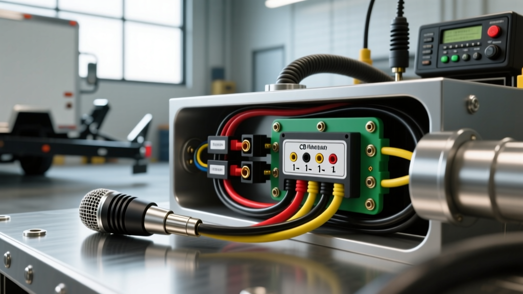
The Critical Role of Intercoms in Trailer Spotting and Convoy Towing
When navigating a 40-foot gooseneck trailer, a multi-axle lowboy, or a fifth-wheel RV into a tight loading dock or campsite, visual clearance from the driver's seat is rarely sufficient. Commercial tow rig operators, heavy-haul fleets, and serious RV enthusiasts rely heavily on CB radios and hardwired spotting intercoms to coordinate maneuvers with ground spotters. At the heart of this communication network is the microphone connector. Understanding the 4 pin mic wiring diagram is critical to eliminating alternator whine, preventing Push-to-Talk (PTT) failures, and ensuring crystal-clear audio when coordinating high-stakes trailer hookups.
In the context of modern tow vehicles, the electrical environment is incredibly hostile to low-voltage audio signals. High-output alternators, PWM (Pulse Width Modulation) trailer brake controllers, and LED trailer lighting harnesses generate severe Electromagnetic Interference (EMI). If your microphone cable is improperly wired or lacks adequate shielding, this EMI will couple into your audio circuit, rendering your intercom useless during critical backing maneuvers. This advanced technical deep dive will explore the exact pinouts, wire specifications, and noise-suppression techniques required to integrate a 4-pin mic system into a heavy-duty tow vehicle.
Standard 4 Pin Mic Wiring Diagram and Pinout Chart
The 4-pin circular microphone connector (often referred to as a 4-pin GD or 4-pin CB mic plug) is the industry standard for most major CB radio manufacturers, including Cobra and Uniden. The wiring harness inside the microphone handles four distinct circuits: audio output (speaker), chassis/shield ground, PTT switching, and audio input (microphone element). Below is the standard pinout configuration for the vast majority of Cobra and Uniden radios used in commercial trucking and tow rigs.
| Pin Number | Function | Standard Wire Color | Signal Type |
|---|---|---|---|
| Pin 1 | Speaker / Audio Out | White | Low-Voltage Analog Audio |
| Pin 2 | Ground / Shield | Bare Copper / Shield | Common Ground / EMI Drain |
| Pin 3 | PTT (Push-to-Talk) | Red | 12V DC Switching Signal |
| Pin 4 | Mic Element / Audio In | Black or Blue | Low-Voltage Analog Audio |
Galaxy and President Radio Pinout Variations
While the Cobra/Uniden standard dominates the market, tow vehicle operators using Galaxy, President, or Texas Ranger radios must exercise caution. These manufacturers frequently utilize a modified 4 pin mic wiring diagram where Pin 1 and Pin 4 are swapped, or where the ground is isolated differently. Always consult the specific service manual for your radio chassis before soldering a replacement mic plug or integrating a secondary intercom handset. Crossing the PTT switching voltage (Pin 3) with the sensitive Mic Element input (Pin 4) will instantly destroy the radio's audio preamplifier IC, requiring a costly bench repair.
Trailer Brake Controllers, PWM Signals, and EMI Interference
Why is a specialized wiring approach necessary for tow vehicles? Modern heavy-duty trucks (such as the Ford F-350, Ram 3500, and Chevrolet Silverado 3500HD) are equipped with integrated or aftermarket trailer brake controllers (e.g., Tekonsha Prodigy P3, Redarc Tow-Pro). These controllers use high-frequency Pulse Width Modulation (PWM) to send variable braking power through the 7-pin RV blade connector to the trailer's electric brakes.
This PWM switching generates significant high-frequency noise on the vehicle's 12V DC bus. According to SAE J1113 Electromagnetic Compatibility Standards, vehicular electrical systems must manage conducted and radiated emissions. However, the unshielded, high-impedance audio input wire of a standard CB microphone acts as an antenna, absorbing this PWM noise. The result is a rhythmic "buzzing" or "whining" sound in the intercom that pulses in time with the trailer brake controller's output or the alternator's RPM. To combat this, the 4-pin mic harness must be constructed with specialized shielded cabling and grounded using a star-ground topology, completely isolated from the brake controller's ground loop.
Wire Gauge, Shielding, and Material Specifications
Standard off-the-shelf replacement mic cords are notoriously inadequate for the EMI-rich environment of a tow vehicle cab. When building a custom 4 pin mic wiring diagram for a spotting intercom or extended CB reach, you must source specialized cable. We recommend a 4-conductor, 22 AWG stranded tinned copper cable wrapped in an aluminum foil shield, complete with a 24 AWG stranded tinned copper drain wire.
| Specification | Requirement for Tow Vehicle Intercoms | Purpose |
|---|---|---|
| Conductor Size | 22 AWG Stranded | Flexibility and durability against cab vibration |
| Shielding | 100% Aluminum Foil + Braided Mesh | Blocks high-frequency PWM noise from brake controllers |
| Drain Wire | 24 AWG Tinned Copper | Provides a dedicated path to ground for EMI dissipation |
| Jacket Material | Polyurethane (PUR) or TPE | Resists UV, extreme cab temperatures, and abrasion |
As noted in the ARRL Grounding and Bonding Guidelines, the shield and drain wire must be terminated at one end only (typically the radio chassis end) to prevent the creation of a ground loop, which will ironically introduce more alternator whine into the audio circuit.
Step-by-Step Installation for Noise-Free Audio
- Prep the Cable: Strip back 2 inches of the PUR outer jacket. Carefully fold the braided shield back and twist the 24 AWG drain wire into a single pigtail.
- Solder the Connections: Do not use crimp connectors inside the 4-pin mic housing. The physical space is too tight, and crimps will fail under the tension of coiled cords. Solder the 22 AWG conductors directly to the mic element, speaker, and PTT microswitch terminals using rosin-core solder.
- Insulate and Protect: Slide 3mm dual-wall adhesive heat shrink tubing over every soldered joint. The inner adhesive layer will seal out moisture and prevent short circuits if the mic is dropped on a wet truck step or exposed to humidity.
- Terminate the Shield: Solder the drain wire to the metal chassis of the microphone housing or the designated Pin 2 ground lug. Ensure the foil shield does not touch any of the active audio or PTT terminals.
- Chassis Grounding at the Radio: When wiring the intercom relay or secondary mic jack at the radio end, ground the drain wire directly to the vehicle's bare metal chassis using a star washer and a self-tapping grounding screw. Never ground the mic shield to the brake controller's ground wire or the radio's negative power lead, as this will inject PWM noise directly into the audio path.
Troubleshooting Decision Tree: Mic and Intercom Faults
When your trailer spotting intercom or CB mic fails in the field, use this diagnostic tree to isolate the fault:
- Symptom: Severe Alternator Whine that changes with engine RPM.
- Cause: Ground loop or unshielded mic cable picking up radiated EMI from the high-output alternator.
- Fix: Verify the mic shield drain wire is grounded to the chassis at one end only. Install a 0.1µF ceramic bypass capacitor across the mic element terminals inside the housing.
- Symptom: Rhythmic Buzzing pulsing with trailer brake application.
- Cause: PWM noise from the trailer brake controller coupling into the 12V DC power supply of the radio, bleeding into the mic preamp.
- Fix: Install an inline LC (Inductor-Capacitor) noise filter on the radio's main 12V power feed. Ensure the radio is wired directly to the battery with an inline fuse, bypassing the dashboard accessory fuse block.
- Symptom: PTT Switch engages, but no audio is transmitted to the spotter.
- Cause: Broken red PTT wire inside the coiled cord (common failure point due to repetitive bending) or oxidized microswitch contacts.
- Fix: Test continuity on Pin 3 while depressing the switch. If open, replace the cord or the microswitch.
- Symptom: Audio is received, but heavily distorted or muffled.
- Cause: Moisture intrusion into the electret condenser microphone element, or Pin 1/Pin 4 swapped (Galaxy vs. Cobra mismatch).
- Fix: Replace the mic element. Verify the 4 pin mic wiring diagram matches your specific radio manufacturer's service manual.
Summary and Regulatory Compliance
Integrating a reliable communication system into a tow vehicle requires far more than simply plugging in a stock plastic microphone. By treating the 4 pin mic wiring diagram as a critical, low-voltage data circuit rather than a simple accessory, fleet managers and owner-operators can eliminate the EMI generated by modern trailer brake controllers and heavy-duty charging systems. Always adhere to FCC Part 95 CB Radio Regulations regarding unauthorized modifications to the radio's internal RF and audio circuitry; all noise suppression and wiring upgrades should be performed on the external cabling and power delivery systems to maintain legal compliance while achieving professional-grade audio clarity on the job site.