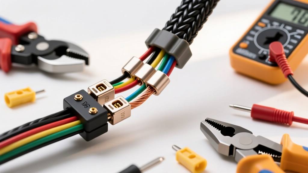
Understanding the 4 Way Wiring Diagram Architecture
When planning a light-duty trailer lighting installation, referencing a standard 4 way wiring diagram is the critical first step. The 4-way flat connector is the industry standard for utility trailers, small boat trailers, and motorcycle trailers under 2,000 lbs GVWR that do not require electric brakes or auxiliary 12V power. Unlike 7-way RV blade connectors, the 4-way flat relies on a simplified circuit architecture that combines the brake and turn signal functions onto a single wire per side, a configuration governed by SAE J586 lighting standards.
However, executing a reliable installation requires more than just splicing wires together. Professional automotive electricians understand that the true cost of a trailer wiring harness involves specialized tools, high-grade materials, and an understanding of modern vehicle multiplexed electrical systems. This guide breaks down the exact tool requirements, material costs, and hidden expenses associated with properly installing a 4-way flat connector system.
Standard Pinout and Wire Color Code Specifications
Before purchasing materials, you must understand the pinout. The physical layout of the 4-way flat connector dictates specific wire color codes and minimum AWG (American Wire Gauge) requirements to prevent voltage drop and overheating. According to Hopkins Manufacturing wiring guides, the standard color code is as follows:
| Pin Position | Function | Standard Wire Color | Minimum AWG (Short Run) | Recommended AWG (20ft+ Run) |
|---|---|---|---|---|
| Pin 1 (Exposed/Ground) | Chassis Ground | White | 16 AWG | 14 AWG |
| Pin 2 | Tail / Running Lights | Brown | 18 AWG | 16 AWG |
| Pin 3 | Left Turn / Stop | Yellow | 18 AWG | 16 AWG |
| Pin 4 | Right Turn / Stop | Green | 18 AWG | 16 AWG |
Note: If your trailer utilizes traditional incandescent bulbs and exceeds 15 feet in length, upgrading to 14 AWG bonded wire for all circuits is highly recommended to mitigate voltage drop, which can cause dim taillights and hyper-flashing turn signals.
Essential Tool Requirements for a Reliable Install
A common failure mode in DIY trailer wiring is the reliance on cheap twist-on connectors or standard vinyl electrical tape. Automotive environments are subjected to extreme vibration, moisture, and road salt. To build a harness that lasts, the following tools are mandatory:
- Ratcheting Wire Crimper: A ratcheting mechanism ensures consistent compression on heat-shrink butt connectors. Non-ratcheting pliers often leave voids inside the crimp barrel, allowing moisture to wick into the copper strands via capillary action.
- Adhesive-Lined Heat Shrink Butt Connectors: Standard vinyl crimps will fail within a year. You must use dual-wall, adhesive-lined heat shrink connectors (typically rated for 16-14 AWG). When heated, the inner meltable adhesive seals the wire insulation, creating a waterproof barrier.
- Dual-Temperature Heat Gun: A lighter or torch will scorch the connector and fail to activate the internal adhesive evenly. A heat gun with a 250°F setting is required to properly shrink the terminals.
- Digital Multimeter (DMM): Essential for verifying 12V reference at the vehicle's tail light harness and diagnosing ground loop issues. A DMM is also required to test for Pulse Width Modulation (PWM) signals on modern vehicles.
- Automatic Wire Strippers: Manual strippers often nick the copper strands. Nicking reduces the wire's cross-sectional area, creating a high-resistance choke point that generates heat and causes voltage drop.
- Dielectric Grease and Star Washers: For the ground connection. Dielectric grease prevents galvanic corrosion, while star washers bite through paint and powder coating to ensure bare metal contact.
Comprehensive Cost Breakdown: Materials and Components
The cost of a 4-way wiring installation varies wildly depending on whether you use a plug-and-play T-connector or a hardwired powered converter. Below is a realistic cost analysis for a professional-grade installation.
| Component Category | Budget / DIY Grade | Professional / Heavy-Duty Grade |
|---|---|---|
| Vehicle-Side Harness (T-Connector) | $15 - $25 (Non-powered tap) | $55 - $85 (Powered ModuLite) |
| Trailer-Side 4-Way Flat Plug | $5 (Hollow pin, vinyl grip) | $14 (Solid pin, molded grip) |
| Bonded Wiring (25 ft spool) | $12 (18 AWG standard) | $28 (14 AWG heavy-duty) |
| Connectors & Terminals | $4 (Vinyl butt splices) | $18 (Adhesive heat-shrink, ring terminals) |
| Consumables (Zip ties, loom, grease) | $5 | $15 |
| Total Estimated Material Cost | $41 - $51 | $130 - $160 |
While the budget route saves money upfront, it almost universally results in troubleshooting headaches down the line. As noted in etrailer's comprehensive wiring FAQ, investing in a powered converter and heavier gauge wire eliminates 90% of common trailer lighting complaints.
The Hidden Cost of Modern Vehicle CAN-Bus and PWM Systems
The most significant hidden cost in modern trailer wiring is dealing with Pulse Width Modulation (PWM) and multiplexed CAN-bus systems. If you are wiring a 2015 or newer half-ton pickup (e.g., Ford F-150, RAM 1500, Chevy Silverado), the vehicle's Body Control Module (BCM) does not send a steady 12V to the tail lights. Instead, it sends a PWM signal—rapidly pulsing the voltage to reduce heat and monitor bulb health.
If you tap a standard 4-way wiring diagram directly into a PWM tail light wire using a cheap $15 tap kit, the trailer lights will strobe, dim, or fail to illuminate entirely. Worse, the added resistance of the trailer bulbs can confuse the BCM into thinking a bulb is out, triggering a dashboard "Trailer Wiring Fault" code and shutting down the circuit entirely.
The Solution and Added Cost: You must install a Powered Tail Light Converter (often branded as ModuLite or ZCI). This device draws power directly from the vehicle's battery via a dedicated 12 AWG power wire and an inline 10A ATO fuse. The vehicle's PWM tail light wires are only used as low-amp signal triggers to activate the converter's internal relays. This adds approximately $40 to your material cost and requires an extra hour of labor to route the power wire through the firewall or along the frame rail to the battery.
Grounding: The Most Common Point of Failure
When analyzing a 4 way wiring diagram, the white ground wire is often treated as an afterthought by amateurs. In reality, the ground circuit carries the return current for all three lighting functions simultaneously. If you are running incandescent bulbs, the ground wire can carry upwards of 8 to 10 amps under heavy braking and running light conditions.
Tapping the white wire into a random rusted bolt or using a self-tapping sheet metal screw is a guaranteed path to failure. The proper installation requires locating a dedicated chassis ground stud or drilling a clean hole in the frame rail. You must sand away all paint, primer, and powder coating down to bare steel. Attach a 14 AWG ring terminal using a stainless steel bolt, a star washer to bite into the metal, and a nylon-insert lock nut. Finally, coat the entire connection in dielectric grease to prevent galvanic corrosion. If the ground fails, the electrical current will seek an alternative path to ground, often backfeeding through the hitch ball, which can fry the vehicle's BCM or cause the trailer's running lights to illuminate when the brakes are pressed.
Final Verdict on Cost vs. Reliability
Executing a proper 4-way flat connector installation is an exercise in electrical best practices. While a basic kit from an auto parts store might only cost $20, the lack of adhesive-lined connectors, insufficient wire gauge, and incompatibility with modern PWM systems will inevitably lead to stranded trailers and blown vehicle fuses. By budgeting between $130 and $160 for professional-grade 14 AWG bonded wire, a powered ModuLite converter, and proper heat-shrink terminals, you ensure a weatherproof, voltage-stable lighting system that complies with SAE standards and survives the harsh realities of the road.