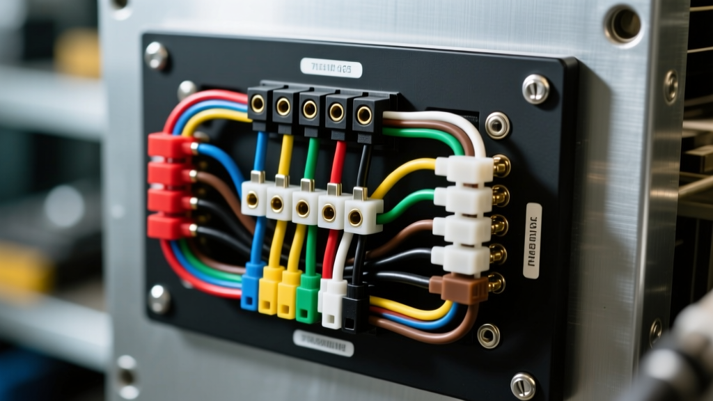
The Anatomy of a 7 Pin Wiring Harness (SAE J286 Standard)
The 7 pin wiring harness, commonly referred to as the 7-way RV blade connector, is the North American standard for heavy-duty towing. Governed by the SAE J286 standard, this configuration provides dedicated circuits for ground, electric brakes, running lights, left/right turn signals, reverse lights, and a 12V auxiliary power feed. When a trailer lighting or brake failure occurs, guessing the problem by swapping bulbs is a waste of time. Professional automotive electricians rely on a systematic, step-by-step troubleshooting flow to isolate voltage drops, open circuits, and galvanic corrosion.
Standard 7-Way Blade Pinout & AWG Specifications
Before testing, verify your harness matches the standard SAE color code and wire gauge requirements. Using undersized wire or Copper-Clad Aluminum (CCA) instead of pure OFC (Oxygen-Free Copper) is a leading cause of voltage drop on brake circuits.
| Pin | Function | Standard Wire Color | Minimum AWG (Copper) |
|---|---|---|---|
| 1 | Ground Return | White | 8 AWG |
| 2 | Electric Brakes | Blue | 10 AWG |
| 3 | Tail / Running Lights | Brown | 12 AWG |
| 4 | 12V Auxiliary / Charge | Black | 10 AWG |
| 5 | Left Turn / Stop | Yellow | 12 AWG |
| 6 | Right Turn / Stop | Green | 12 AWG |
| 7 | Reverse / Backup Lights | Red or Purple | 12 AWG |
Essential Diagnostic Tools
- Digital Multimeter (DMM): Must be capable of measuring DC Voltage, Continuity, and Duty Cycle (for PWM brake signals).
- Incandescent Test Light: Preferred over LED testers for checking lighting circuits, as it draws a physical load to reveal high-resistance connections.
- Tow Vehicle Socket Tester: A plug-in 7-way LED diagnostic tool for rapid vehicle-side verification.
- Dielectric Grease: Nyogel 760G or equivalent marine-grade silicone grease to prevent oxidation post-repair.
Phase 1: Vehicle-Side Socket Verification (The Source)
Never begin troubleshooting at the trailer lights. You must first confirm the tow vehicle is outputting the correct signals. Plug your diagnostic socket tester into the vehicle's 7-way receptacle. If a tester is unavailable, use your DMM set to DC Volts.
- Ground Verification: Place the DMM black probe on a known good engine ground and the red probe on Pin 1. It should read 0.00V to 0.05V. Any higher indicates a vehicle-side ground fault.
- Running Lights (Pin 3): Turn on the tow vehicle headlights. Probe Pin 3. You must read >12.4V (engine off) or >13.8V (engine running).
- Turn Signals (Pins 5 & 6): Activate the hazard lights. Probe Pins 5 and 6. The voltage should pulse from 0V to 12V in time with the hazard flasher.
- Auxiliary Power (Pin 4): Probe Pin 4. This should have constant battery voltage. Note: Many modern trucks (2015+) require the factory tow package to be configured via the OEM diagnostic scan tool to enable the Pin 4 relay.
Decision Point: If the vehicle socket fails any of these tests, the issue is in the tow vehicle's wiring, fuses, or factory brake controller module. Consult Curt Manufacturing's vehicle-specific wiring guides for OEM module locations. If the socket passes, proceed to Phase 2.
Phase 2: Isolating the Ground Circuit (Pin 1)
Over 70% of all trailer wiring anomalies—including dim lights, back-feeding, and erratic brake controller behavior—stem from a compromised Pin 1 ground. The white ground wire must provide a zero-resistance path back to the tow vehicle battery negative terminal.
The Jumper Wire Bypass Test
To definitively rule out the trailer's ground wire and chassis connection:
- Disconnect the trailer's 7-way plug from the tow vehicle.
- Run a heavy-gauge (8 AWG or 10 AWG) jumper wire directly from the tow vehicle's battery negative terminal to a clean, bare-metal spot on the trailer's steel frame.
- Reconnect the 7-way plug and test the malfunctioning circuit.
Result Analysis: If the circuit functions perfectly with the jumper wire installed, your Pin 1 ground is faulty. You must strip the white wire's ring terminal, sand the trailer frame down to bare steel, apply a zinc-rich anti-corrosion compound, and torque the 5/16" grounding bolt to 10-15 ft-lbs. Re-seal with dielectric grease.
Phase 3: Lighting and Signal Circuit Testing (The Load)
If the ground is verified and the vehicle socket is outputting correctly, the fault lies within the trailer's wiring harness, junction box, or light assemblies.
Voltage Drop Testing at the Junction Box
Most enclosed and utility trailers utilize a sealed junction box where the heavy-gauge 7 pin wiring harness transitions to lighter gauge wires routed to the individual lamps.
- Open the trailer junction box.
- Set your DMM to DC Volts.
- With the tow vehicle's running lights ON, place the red probe on the brown wire terminal inside the junction box and the black probe on the white ground terminal.
- Compare this reading to the voltage at the vehicle socket (Pin 3).
Diagnostic Rule: A voltage drop greater than 0.5V between the vehicle socket and the trailer junction box indicates high resistance in the trailer's main harness (likely a corroded plug pin or a crimped/broken wire inside the insulation). A voltage drop greater than 1.0V between the junction box and the physical tail light indicates a faulty wire run along the trailer frame.
Phase 4: Electric Brakes (Pin 2) and PWM Signals
Testing the electric brake circuit (Blue wire, Pin 2) requires an understanding of modern brake controllers. Proportional brake controllers do not output a steady 12V DC signal; they output a Pulse Width Modulated (PWM) signal to vary the braking force based on vehicle deceleration.
Why Your Multimeter is Giving You False Readings
If you probe Pin 2 with a standard DMM while manually sliding the brake controller override lever, you may see erratic voltage readings (e.g., bouncing between 4V and 9V). This is normal for a PWM signal.
- Correct Testing Method 1 (Test Light): Use an incandescent test light. Connect the alligator clip to Pin 1 (Ground) and probe Pin 2. Pull the manual override lever on the brake controller. The test light should illuminate brightly and steadily.
- Correct Testing Method 2 (DMM Duty Cycle): Set your advanced DMM to measure Duty Cycle (%). Pull the override lever. A reading between 85% and 99% duty cycle indicates the controller is commanding maximum braking force.
For comprehensive brake controller installation and diagnostic protocols, refer to the Tekonsha installation and troubleshooting documentation.
Testing the Brake Magnets (Trailer Side)
If voltage is reaching the trailer junction box on the blue wire, but the brakes are weak or non-existent, test the individual brake magnets.
- Jack up the trailer and remove the wheel and brake drum.
- Locate the two wires exiting the brake backing plate.
- Set the DMM to Ohms (Resistance).
- Measure across the two magnet wires. A healthy 10" or 12" electric brake magnet should read between 3.0 and 4.0 Ohms.
- If the meter reads OL (Open Loop), the magnet coil is burnt out and must be replaced. If it reads near 0.0 Ohms, the magnet is internally shorted.
Advanced Diagnostics: Auxiliary Power (Pin 4) Failures
Pin 4 (Black wire) is frequently used to charge the trailer's breakaway battery or power interior lights and winches. If you have 12V at the vehicle socket but 0V at the trailer junction box, check the following:
- Under-Hood Fuses and Relays: Most OEM tow packages route the Pin 4 feed through a dedicated 30A or 40A maxi-fuse and a high-amperage relay located in the engine bay power distribution center.
- Breakaway Switch Interference: Ensure the trailer's breakaway pin is fully inserted. On some poorly designed trailer junction boxes, a partially seated breakaway pin can back-feed 12V from the trailer battery onto the blue brake circuit, causing the brakes to lock up and blowing the tow vehicle's brake controller fuse.
Common 7 Pin Wiring Harness Failure Modes & Permanent Fixes
1. Galvanic Corrosion at the Plug: The mating pins inside the 7-way plug are often brass or tin-plated, while the socket uses different metals. Moisture ingress causes electrolysis. Fix: Pull the pins out of the rubber housing, clean them with electrical contact cleaner, lightly sand them, and pack the entire plug cavity with marine-grade dielectric grease before reassembly.
2. The "Trailer Tap" Splice Failure: Many DIYers use Scotchlok T-taps to splice into the trailer's running light wire. These pierce the insulation, exposing the copper strand to moisture, leading to green copper oxide (verdigris) that acts as a semiconductor, blocking current flow. Fix: Cut out all T-taps. Use adhesive-lined, heat-shrink butt connectors and a proper crimping tool to seal the connection from oxygen and water.
3. Wire Fatigue at the Articulation Point: The section of the 7 pin wiring harness between the trailer tongue and the A-frame junction box is subject to extreme flexing during turning. Over time, the copper strands snap inside the intact PVC insulation. Fix: Replace the entire tongue pigtail. Do not attempt to patch flex-zone wiring. Install a flexible conduit loom over the replacement harness to protect against road debris and UV degradation.