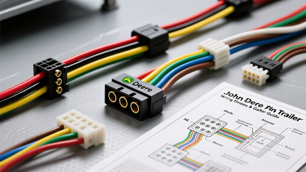
Understanding the John Deere 7 Pin Wiring Diagram
When hooking up a trailer to your John Deere equipment, the most common point of confusion is identifying the correct 7-pin configuration. Unlike standard pickup trucks that universally use a single 7-way connector, John Deere utilizes two entirely different 7-pin standards depending on the vehicle class. If you are wiring a John Deere Gator or compact utility vehicle, you will typically use the standard RV 7-way blade connector. However, if you are operating a John Deere agricultural or commercial tractor (such as the 5M, 6R, or 8R series), the factory harness uses a 7-pin round connector governed by ISO 1185 standards.
Misunderstanding these two systems is the leading cause of blown fuses, short circuits, and non-functional trailer lights. This beginner-friendly guide breaks down both John Deere 7 pin wiring diagrams, providing exact wire colors, AWG specifications, and professional installation techniques to ensure your trailer lights and brakes operate safely in the field and on the highway.
Type 1: Standard 7-Way RV Blade (Gator & Utility Vehicles)
For John Deere Gators (like the XUV835E or HPX series) and smaller compact tractors fitted with aftermarket or dealer-installed tow packages, the standard 7-way RV blade connector is the norm. This connector follows the SAE J286 standard, which is identical to what you will find on a Ford F-150 or Chevy Silverado. It supports standard lighting, 12-volt auxiliary power, and electric trailer brakes.
RV 7-Way Blade Pinout and Wire Specifications
| Pin Position | Function | Standard Wire Color | Recommended AWG |
|---|---|---|---|
| Pin 1 (White) | Ground (Chassis/Battery) | White | 10 AWG |
| Pin 2 (Blue) | Electric Trailer Brakes | Blue | 12 AWG |
| Pin 3 (Green) | Tail, License, and Running Lights | Green | 14 AWG |
| Pin 4 (Black) | 12V Auxiliary / Battery Charge | Black | 12 AWG |
| Pin 5 (Red) | Left Turn Signal & Stop Lights | Red | 14 AWG |
| Pin 6 (Brown) | Right Turn Signal & Stop Lights | Brown | 14 AWG |
| Pin 7 (Yellow) | Backup / Reverse Lights | Yellow | 14 AWG |
Note: Always run the white ground wire (Pin 1) directly to the vehicle battery negative terminal or a dedicated, unpainted chassis ground bolt. John Deere Gator frames are heavily powder-coated, which prevents standard grounding screws from making a solid electrical connection.
Type 2: ISO 1185 7-Pin Round (Agricultural Tractors)
If you are looking at the rear of a larger John Deere row-crop or utility tractor, you will see a heavy-duty, round 7-pin socket with a twist-lock cover. This is not an RV connector. It conforms to the ISO 1185 standard for agricultural and forestry vehicles. This connector is designed strictly for lighting and does not carry the heavy amperage required for electric trailer brakes (which require a separate ISO 7638 ABS/Brake socket on modern tractors).
Because agricultural environments expose wiring to extreme moisture, mud, and corrosive fertilizers, the ISO 1185 standard utilizes metric wire sizing (mm²) rather than American Wire Gauge (AWG), and the pin functions are completely different from the RV blade.
ISO 1185 Ag Tractor Pinout and Wire Specifications
| Pin Number | Function | ISO Standard Wire Color | Cross-Section (mm² / AWG) |
|---|---|---|---|
| Pin 1 | Left Turn Signal | Yellow | 1.5 mm² (~14 AWG) |
| Pin 2 | Rear Fog Light / Work Light | Blue | 1.5 mm² (~14 AWG) |
| Pin 3 | Ground (Return Line) | White | 2.5 mm² (~12 AWG) |
| Pin 4 | Right Turn Signal | Green | 1.5 mm² (~14 AWG) |
| Pin 5 | Right Tail, Marker, & License Lights | Brown | 1.5 mm² (~14 AWG) |
| Pin 6 | Stop / Brake Lights | Red | 1.5 mm² (~14 AWG) |
| Pin 7 | Left Tail, Marker, & License Lights | Black | 1.5 mm² (~14 AWG) |
Crucial Beginner Tip: Never plug a standard RV 7-way adapter into an ISO 1185 tractor socket without a specialized, wired converter box. Doing so will cross the ground and 12V power circuits, instantly blowing the tractor's main lighting fuse or damaging the CANbus electrical system.
Best Practices for Splicing and Installation
Whether you are repairing a frayed harness on your Gator or building a custom adapter for your tractor, the longevity of your wiring depends entirely on your splicing methods. Agricultural environments are unforgiving. Follow these professional-grade steps to prevent future failures:
- Use Heat-Shrink Butt Connectors: Never use standard vinyl crimp connectors or twist-on wire nuts. Use marine-grade, adhesive-lined heat-shrink butt connectors. When heated, the internal adhesive melts and seals the wire strands against moisture and corrosion.
- Apply Dielectric Grease: Coat the male pins and female sockets of your 7-pin connectors with a high-quality silicone dielectric grease. This prevents galvanic corrosion between the brass pins and the socket contacts, which is a common failure point on John Deere equipment exposed to liquid fertilizers.
- Upgrade the Ground Wire: Factory trailer ground wires are notoriously undersized. Upgrade the ground circuit to 10 AWG wire and ring-terminal it directly to the trailer frame. Sand the paint off the frame down to bare, shiny metal before attaching the ring terminal, and coat the connection with clear nail polish or rust-inhibitor spray to prevent oxidation.
- Loom and Zip-Tie: Protect your wiring harness with split-loom tubing. Secure the loom every 12 inches using UV-resistant zip ties, ensuring the harness has enough slack to articulate fully without pulling taut when the tractor or Gator turns sharply.
Troubleshooting Common John Deere Trailer Light Issues
When your trailer lights fail, do not immediately assume the 7-pin socket is broken. Use this diagnostic decision tree to isolate the fault quickly:
Symptom: Trailer Running Lights Work, but Turn Signals/Brakes Do Not
- Cause: Poor ground connection or blown vehicle-side fuse. Turn signals draw more amperage than LED running lights. A weak ground can support low-amp running lights but will choke under the load of brake/turn circuits.
- Fix: Clean the trailer frame ground point. If the ground is solid, check the John Deere fuse panel (usually located under the hood or behind the operator seat) for the specific left/right trailer turn fuses.
Symptom: Tractor Dashboard Displays "Lighting Short" or Blows Fuse Immediately
- Cause: Exposed wiring on the trailer tongue pinching against the metal hitch, or water intrusion inside the trailer's junction box.
- Fix: Unplug the 7-pin connector. Inspect the trailer tongue for crushed wiring. Open the trailer's front junction box and look for green corrosion on the wire nuts or terminal strips. Replace with heat-shrink connectors.
Symptom: Gator Electric Trailer Brakes Lock Up When Headlights Are Turned On
- Cause: Cross-wired pins or a "backfeed" ground issue. If the ground wire (Pin 1) is disconnected or highly resistant, the electrical current from the running lights (Pin 3) will seek an alternative path to ground, often backfeeding through the electric brake circuit (Pin 2).
- Fix: Test the white ground wire with a multimeter for continuity to the battery negative terminal. Repair the ground connection immediately to prevent brake overheating and fires.
Summary and Technical References
Understanding the difference between the SAE J286 RV blade and the ISO 1185 agricultural round connector is the fundamental first step in mastering John Deere trailer wiring. By respecting wire gauge requirements, prioritizing heavy-duty ground connections, and using marine-grade splicing techniques, you can build a trailer lighting system that survives the harshest farming and utility conditions. For deeper diagnostic procedures, always consult your specific vehicle's operator manual or reference the John Deere Technical Publications portal for factory wiring schematics.