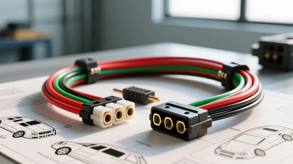
Electrical Characteristics of LED vs. Incandescent Trailer Lighting
Transitioning from incandescent bulbs to LED assemblies fundamentally alters the electrical topology of a trailer harness. When consulting an LED trailer lights wiring diagram, technicians must account for the absence of thermal inertia, significantly lower amperage draw, and heightened sensitivity to voltage drop and multiplexed signals. Unlike a standard 1157 incandescent bulb that draws approximately 2.1 amps on the stop/turn circuit, a modern LED equivalent draws between 0.15A and 0.30A. While this reduces alternator load and minimizes voltage drop across long harness runs, it introduces complex compatibility issues with modern Body Control Modules (BCMs) that utilize Pulse Width Modulation (PWM) and CANbus load-detection algorithms.
This technical specification reference provides the exact pinouts, wire gauge requirements, and failure-mode diagnostics necessary for properly integrating LED trailer lighting into both legacy and late-model tow vehicles.
4-Way Flat Connector Pinout & LED Specifications
The 4-way flat connector remains the standard for light-duty utility, boat, and small cargo trailers. When wiring LED assemblies, the physical pinout remains identical to incandescent systems, but the wire gauge and grounding methodology must be optimized for the low-current, high-sensitivity nature of semiconductor diodes.
| Pin / Terminal | Function | Standard Wire Color | Min. AWG (25ft Run) | Typical LED Amp Draw |
|---|---|---|---|---|
| 1 (Ground) | Chassis Ground | White | 12 AWG | N/A (Return Path) |
| 2 (Tail/Running) | Clearance & Tail Lights | Brown | 16 AWG | 0.10A - 0.25A |
| 3 (Left Stop/Turn) | Left Brake & Turn Signal | Yellow | 16 AWG | 0.15A - 0.30A |
| 4 (Right Stop/Turn) | Right Brake & Turn Signal | Green | 16 AWG | 0.15A - 0.30A |
Expert Note: While 18 AWG wire is often included in pre-fabricated LED harness kits, the SAE J1128 standard for low-tension primary cable recommends stepping up to 16 AWG for the main harness to prevent mechanical failure from vibration and to ensure adequate current capacity for future accessory additions.
7-Way RV Blade Connector Pinout & LED Specifications
The 7-way RV blade connector is mandatory for heavy-duty towing, travel trailers, and fifth-wheels. This configuration separates the electric brake controller circuit and the 12V auxiliary power circuit from the lighting circuits. The LED lighting circuits (Tail, Left Stop, Right Stop) follow the same low-amperage parameters as the 4-way, but the overall harness requires heavier gauge wiring to support the non-LED auxiliary loads.
| Pin (Clock Face) | Function | Standard Wire Color | Min. AWG | Technical Notes for LED Integration |
|---|---|---|---|---|
| 7:00 (Ground) | System Ground | White | 10 AWG | Must be bonded directly to trailer frame; do not rely on hitch ball ground. |
| 11:00 (Tail) | Running/Clearance | Brown | 14 AWG | Carries up to 15+ LED clearance markers; voltage drop is a primary concern. |
| 9:00 (Left) | Left Stop/Turn | Yellow | 14 AWG | Subject to CANbus hyperflashing if BCM expects incandescent load. |
| 3:00 (Right) | Right Stop/Turn | Green | 14 AWG | Subject to CANbus hyperflashing if BCM expects incandescent load. |
| 5:00 (Brakes) | Electric Trailer Brakes | Blue | 10 AWG | Not an LED circuit; carries up to 12A+ for tandem axle brake magnets. |
| 1:00 (Aux) | 12V Auxiliary Power | Black | 10 AWG | Used for interior lights, winches, or battery charging. |
| Center | Auxiliary / Reverse | Red or Purple | 14 AWG | Often used to power LED reverse flood lights or bypass surge brakes. |
Multiplexed PWM Systems and LED Compatibility
One of the most pervasive issues encountered when following an LED trailer lights wiring diagram on modern trucks (specifically 2015+ Ford F-150s, 2019+ Ram 1500s, and late-model GM HDs) is LED flickering or strobing. This is not a defect in the LED assembly; it is a byproduct of the vehicle's trailer lighting module utilizing Pulse Width Modulation (PWM) for diagnostics.
The BCM rapidly switches the power circuit on and off (typically at frequencies between 400Hz and 1000Hz) to monitor current flow and detect shorts or open circuits. An incandescent bulb's filament retains heat during the 'off' micro-cycles, appearing as a solid, continuous light to the human eye. An LED semiconductor, however, reacts in nanoseconds, turning completely off during the micro-cycles, resulting in a visible strobe effect or a failure to illuminate entirely if the PWM duty cycle is too low.
The Technical Fix: Inline PWM Filters
To resolve PWM flickering without disabling the vehicle's tow-module diagnostics, an inline PWM filter (bypass capacitor module) must be installed on the trailer side of the harness. These modules absorb the PWM pulses and release a smooth, continuous DC voltage to the LED driver boards. Install the filter as close to the trailer connector as possible, ensuring the ground wire is secured to a clean, bare-metal point on the trailer tongue.
CANbus Load Detection and Hyperflashing
Modern vehicles use the CANbus network to monitor the electrical load of the trailer lighting circuits. If the BCM detects an amperage draw below its programmed threshold (expecting 2.1A but seeing 0.2A from an LED), it assumes a bulb is out and triggers a hyperflash (rapid blinking) on the dashboard and the trailer turn signals.
Resolution Protocols:
- Load Resistors: Wiring 50-watt, 6-ohm load resistors in parallel with the LED turn signal circuits simulates the missing incandescent load. Warning: Resistors generate extreme heat and must be mounted to a metal surface, away from plastic wire looms.
- CANbus Decoders: An electronic CANbus decoder module is preferred for LED setups. These solid-state modules trick the BCM into reading a normal load without generating parasitic heat.
- BCM Flash/Reprogramming: Some dealerships can flash the tow vehicle's BCM to switch the trailer lighting profile from 'Incandescent' to 'LED', eliminating the need for external resistors.
Voltage Drop and Grounding Requirements for LED Assemblies
LED driver boards require a minimum threshold voltage (typically 10.5V to 11.0V) to activate. If the wiring harness suffers from excessive voltage drop, the LEDs may fail to illuminate, flicker, or exhibit 'ghosting'—where applying the brakes causes the tail lights to dimly illuminate due to current backfeeding through a poor ground.
According to Grote Industries engineering whitepapers, relying on the hitch ball and coupler for a ground path is unacceptable for LED trailers. Corrosion, paint, and articulation resistance will starve the LED circuits of a clean return path.
Proper Grounding Protocol
- Run a dedicated 10 AWG or 12 AWG white ground wire from the trailer connector directly to the trailer frame.
- Use a star washer and ring terminal to secure the ground to bare, sanded metal on the frame.
- Run individual 14 AWG ground pigtails from every single LED clearance marker and tail light assembly directly to the main frame or a dedicated copper ground bus bar. Do not rely on the stainless steel screws mounting the light to painted aluminum or steel to complete the circuit.
LED Trailer Light Troubleshooting Matrix
Use the following diagnostic matrix to resolve common anomalies encountered after executing an LED trailer lights wiring diagram installation.
| Symptom | Root Cause Analysis | Technical Resolution |
|---|---|---|
| LEDs strobe or flicker rapidly | Tow vehicle BCM utilizes PWM for short-circuit detection. | Install inline PWM filter module on trailer harness. |
| Turn signals blink twice as fast (Hyperflash) | CANbus detects low amp draw of LEDs and assumes blown bulb. | Install 6-ohm load resistors in parallel, or flash BCM for LED profile. |
| Tail lights illuminate when brakes are pressed (Ghosting) | High resistance on white ground wire forcing current to backfeed through tail circuit. | Scrape paint from frame, install dedicated 12 AWG ground wire with star washer. |
| Clearance lights fail to illuminate at dusk | Voltage drop across 18 AWG brown wire over long trailer run drops below 10.5V LED threshold. | Replace main brown harness wire with 14 AWG or 12 AWG stranded copper. |
| LEDs illuminate dimly when connected to running lights | Corrosion inside the 4-pin/7-pin plug increasing contact resistance. | Clean terminals with dielectric cleaner, apply silicone dielectric grease, and bend prongs for tighter tension. |
Conclusion and Best Practices
Wiring a trailer for LED lighting requires a shift in diagnostic thinking. By adhering to proper AWG sizing, implementing dedicated frame grounding, and addressing modern BCM multiplexing via PWM filters, you can build a trailer lighting harness that is immune to the vibration, moisture, and electrical noise that destroy legacy incandescent systems. For further reading on heavy-duty 7-way configurations and commercial air-over-electric systems, refer to the etrailer wiring FAQ and technical guides for vehicle-specific adapter pinouts.