Understanding the SAE J560 Standard for Class 8 Vehicles
When outfitting or repairing Class 8 commercial trucks, relying on a consumer-grade wiring harness is a critical safety hazard. The semi 7 pin wiring diagram is governed by the SAE J560 standard, which dictates the physical dimensions, pin configurations, and electrical requirements for heavy-duty truck-to-trailer connections. Unlike standard recreational vehicle (RV) setups, the SAE J560 standard is engineered to handle the rigorous demands of commercial freight, including high-amperage lighting arrays, continuous clearance light draws, and the strict anti-lock braking system (ABS) power requirements mandated by the National Highway Traffic Safety Administration (NHTSA) under FMVSS 121.
Selecting the correct cable assembly and understanding the precise pinout is not just about making the lights work; it is about preventing voltage drop, avoiding catastrophic harness fires, and ensuring that the trailer ABS module receives the necessary inrush current during initial ignition startup. In this comprehensive product comparison and selection guide, we break down the technical specifications of the semi 7-pin system, compare commercial versus consumer 7-way connectors, and evaluate heavy-duty cable materials for extreme operating environments.
The Semi 7 Pin Wiring Diagram & Pinout Chart
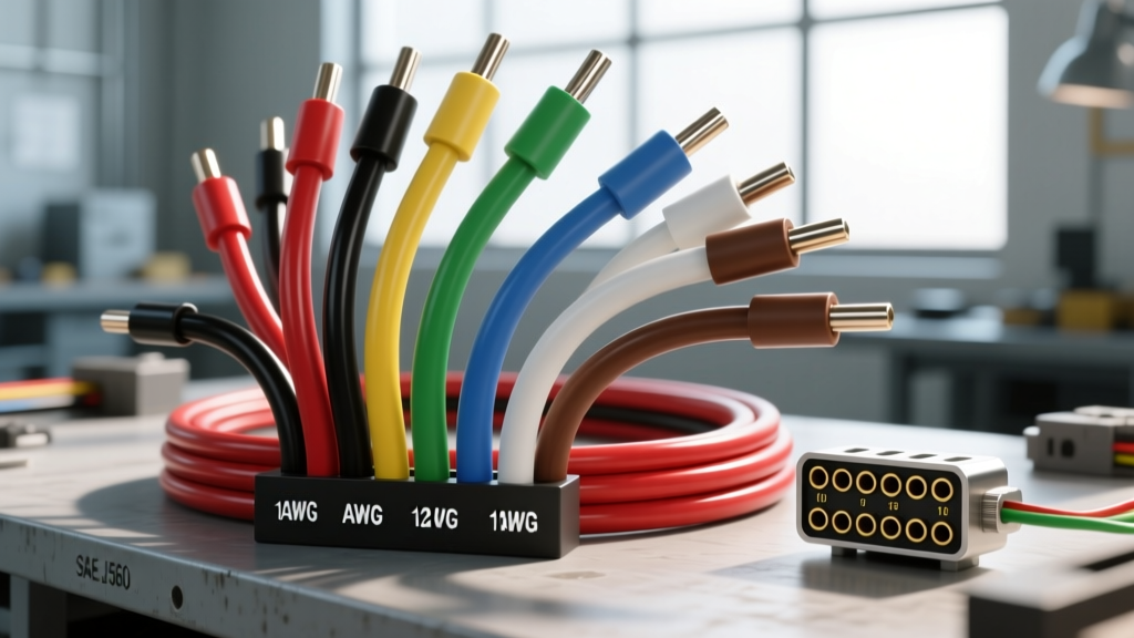
The SAE J560 connector utilizes a specific color code and wire gauge requirement that differs vastly from consumer applications. The ground circuit requires a heavier gauge to accommodate the cumulative return current of all trailer lighting and the ABS electronic control unit (ECU). Below is the definitive pinout chart for the commercial semi 7-pin receptacle, viewed from the mating face of the trailer-side plug.
| Pin Number | Function | Standard Wire Color | Minimum AWG Size | Typical Amperage Draw |
|---|---|---|---|---|
| 1 | Ground / Return | White | 8 AWG | 30A - 50A (Cumulative) |
| 2 | Clearance / Marker Lights | Black | 10 AWG | 10A - 15A |
| 3 | Left Turn Signal | Yellow | 10 AWG | 8A - 12A |
| 4 | Stop Lamps / Brakes | Red | 10 AWG | 15A - 20A |
| 5 | Right Turn Signal | Green | 10 AWG | 8A - 12A |
| 6 | Tail / Running Lamps | Brown | 10 AWG | 10A - 15A |
| 7 | Auxiliary / ABS Power | Blue | 10 AWG | 15A (Inrush), 4A (Continuous) |
Note: Always verify pinouts with a digital multimeter before mating a new cable assembly. Previous owner modifications or non-standard adapter usage can alter factory wiring configurations.
Commercial Semi 7-Pin vs. RV 7-Way: Critical Differences
A frequent and dangerous mistake made by owner-operators and fleet maintenance technicians is attempting to cross-reference or adapt an RV 7-way (RVIA standard) harness to a commercial SAE J560 semi-tractor. While the physical 7-pin circular connectors may look nearly identical to the untrained eye, the internal pinouts and wire gauges are entirely different.
The Danger of Pinout Mismatches
In the consumer RVIA standard, Pin 2 is typically 12V Auxiliary Power, and Pin 4 is the Left Turn/Stop circuit. In the commercial SAE J560 semi 7 pin wiring diagram, Pin 2 is Clearance Lights, and Pin 4 is the dedicated Stop Lamp circuit. Furthermore, the RV standard utilizes a 12 AWG to 16 AWG wire for most circuits, whereas the semi standard mandates 10 AWG (and an 8 AWG ground).
If you plug an RV-style cord into a commercial semi-tractor without a properly wired, gauge-rated step-down adapter, you will instantly send heavy amperage down the RV's 14 AWG clearance wire, melting the harness and potentially igniting a fire in the trailer's sub-floor. Conversely, the commercial trailer's ABS module (Pin 7) will starve for current if fed through an RV harness, resulting in continuous ABS fault codes and potential DOT compliance violations during roadside inspections.
Product Comparison: Selecting the Right 7-Pin Cable Assembly
When sourcing replacement cables or upgrading a fleet, the market offers various configurations. Selecting the right product requires analyzing the jacket material, coil memory, and terminal construction.
Jacket Material: PVC vs. TPE (Hytrel)
- Standard PVC (Polyvinyl Chloride): PVC-jacketed cables are cost-effective and perform adequately in moderate climates. However, PVC becomes highly rigid and brittle at temperatures below 20°F (-6°C). In winter freight operations, a stiff PVC cable can snap or pull out of the receptacle when the truck navigates tight dock corners.
- TPE / Hytrel (Thermoplastic Elastomer): Premium heavy-duty cables utilize TPE jackets. TPE remains highly flexible down to -40°F (-40°C). For fleets operating in the Midwest or Northern corridors, TPE is a mandatory specification to prevent jacket cracking and internal copper strand fracturing caused by extreme cold and mechanical tension.
Cable Configuration: Coiled vs. Straight
The industry standard for semi-trucks is the 15-foot coiled cable, which provides a working length of approximately 5 to 7 feet. This coil memory acts as a mechanical shock absorber. When selecting a coiled cable, look for over-molded strain reliefs at both the tractor and trailer plugs. Cheaply manufactured cables rely solely on a set-screw inside the plug housing to hold the cable, which inevitably leads to the 8 AWG ground wire tearing free from Pin 1 under heavy vibration.
Connector Housing: Die-Cast Zinc vs. Polycarbonate
While high-impact polycarbonate plugs are common and resist corrosion, die-cast zinc housings are the superior choice for high-abuse environments. Zinc housings dissipate heat better during high-amperage draws (such as when all LED marker lights and brake lights are illuminated simultaneously) and are less likely to crack if struck by road debris or dropped on concrete during coupling.
Voltage Drop, ABS Inrush, and 53-Foot Trailer Dynamics
Understanding the SAE J560 Standard requires an understanding of voltage drop over distance. A standard 53-foot dry van trailer requires roughly 60 feet of wiring from the tractor receptacle to the rear ABS ECU and lighting harness.
When the ignition is turned on, the trailer ABS module performs a self-diagnostic lamp check, drawing an inrush current of up to 15 amps for a fraction of a second. Using the voltage drop formula (VD = 2 x K x L x I / CM), a standard 10 AWG copper wire (10,380 circular mils) over a 60-foot run will experience a voltage drop of approximately 1.04 volts. While this is within the acceptable threshold to keep the ABS ECU happy (requiring a minimum of 9.5V at the module), using undersized 12 AWG repair wire for Pin 7 will cause the voltage to drop below 8.5V, triggering a ghost ABS fault code on the tractor dashboard.
According to Phillips Industries, a leading manufacturer of commercial vehicle electrical systems, maintaining strict adherence to 10 AWG and 8 AWG wire sizes across the entire length of the trailer harness is the only way to ensure FMVSS 121 compliance and reliable braking telemetry.
Real-World Troubleshooting & Installation Torque Specs
Even with the correct semi 7 pin wiring diagram and premium TPE cables, failure modes occur due to improper installation techniques. Below is a troubleshooting and installation guide for fleet mechanics.
Terminal Set-Screw Torque Specifications
When terminating raw cable into a new J560 plug, the set-screws that bite into the stripped copper strands must be torqued correctly. Under-tightening causes micro-arcing, which oxidizes the copper and creates a high-resistance hotspot. Over-tightening severs the outer strands of the 10 AWG wire, reducing the effective cross-sectional area and causing voltage drop.
- Recommended Torque: 12 to 15 inch-pounds.
- Preparation: Strip exactly 3/8-inch of insulation. Do not tin the wire with solder; solder creeps under vibration and loosens the set-screw connection over time.
- Corrosion Prevention: Apply a liberal amount of dielectric grease or anti-oxidant compound (e.g., Noalox) to the pin entry points to prevent galvanic corrosion between the copper wire and the brass/zinc terminal.
Symptom-Cause-Fix Decision Tree
- Symptom: Trailer ABS light remains illuminated on the dash; left turn signal hyper-flashes.
- Cause: High resistance on Pin 1 (Ground). The ABS module is attempting to ground through the Pin 3 (Left Turn) circuit, backfeeding voltage into the tractor's flasher relay.
- Fix: Inspect the 8 AWG White wire termination at both the tractor receptacle and trailer plug. Clean the brass pin with a fiberglass scratch brush and verify the ground eyelet is securely bolted to the trailer chassis with a star washer to bite through paint and rust.
- Symptom: Clearance lights (Pin 2) flicker only when the service brakes (Pin 4) are applied.
- Cause: Melting or shorting between the Black and Red wire insulation inside the trailer's rear harness junction box, caused by previous use of undersized 14 AWG wire generating excess heat.
- Fix: Replace the rear jumper harness with a fully sealed, 10 AWG SAE J560 compliant harness and inspect the plug housing for heat deformation.
Authoritative References & Further Reading
For fleet managers and owner-operators looking to deep-dive into federal mandates and manufacturing specifications, consult the following resources: