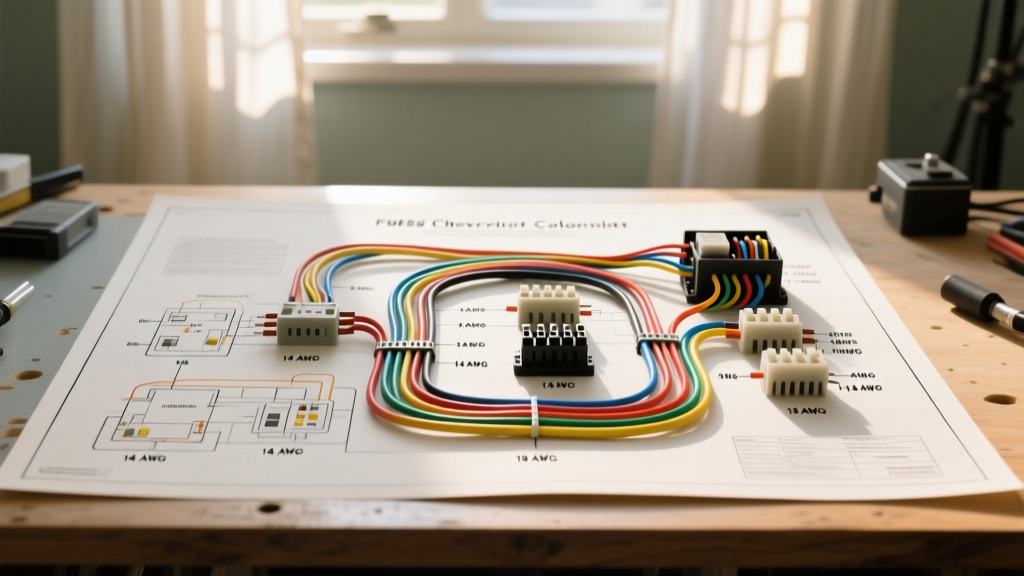
Decoding the 1966 Chevrolet Color Wiring Diagram for Modern Mods
Restomodding a 1966 Chevrolet—whether it is an Impala, Chevelle, Biscayne, or C10 pickup—requires a deep understanding of the original electrical architecture. The factory harness was designed for a 40-amp generator or an early externally regulated 10DN alternator, points-style ignition, and low-draw sealed beam headlights. When you introduce modern high-amperage accessories, electronic fuel injection, or high-energy ignition systems, relying on a 50-year-old wiring map without modifications is a recipe for melted bulkheads and voltage drop. Utilizing a comprehensive 1966 Chevrolet color wiring diagram is the critical first step in safely integrating modern upgrades while retaining the classic aesthetic of the engine bay and dash.
This technical guide breaks down the factory General Motors A-Body, B-Body, and C/K truck color codes, American Wire Gauge (AWG) specifications, and connector types. We will outline three essential upgrade projects: converting to a 1-wire alternator, swapping to an HEI distributor, and integrating high-amperage headlight relays.
Factory Baseline: Key OEM Wire Colors and AWG Specifications
Before cutting into a single wire, you must map the OEM circuits. The 1966 GM passenger car and light truck forward lamp and dash harnesses share a standardized color palette. Below is the definitive reference chart for the primary circuits you will interact with during a restomod build.
| Circuit Function | OEM Wire Color | Factory AWG | Origin / Destination |
|---|---|---|---|
| Main Battery Feed | Red | 10 AWG | Battery to Horn Relay Buss |
| Alternator Charge | Red | 10 AWG | Alternator BAT to Horn Relay |
| Ignition Switch (Run) | Pink | 12 AWG (Resistive) | Ignition Sw. to Coil (+) |
| Headlights (Low Beam) | Light Green | 14 AWG | Dimmer Sw. to Front Lamps |
| Headlights (High Beam) | Dark Blue | 14 AWG | Dimmer Sw. to Front Lamps |
| Parking / Taillights | Brown | 14 AWG | Light Sw. to Rear Harness |
| Left Stop / Turn | Yellow | 14 AWG | Turn Signal Sw. to Rear |
| Right Stop / Turn | Dark Green | 14 AWG | Turn Signal Sw. to Rear |
| Instrument Cluster Feed | White | 16 AWG | Light Sw. to Dash PCB |
Note: Wire specifications align with historical GM service manuals and modern SAE J1128 Low Tension Primary Cable standards for automotive cross-linked polyethylene (XLPE) insulation.
Upgrade Project 1: 1-Wire Alternator Conversion
The 1966 Chevrolet originally utilized a Delco 10DN alternator paired with an external voltage regulator mounted on the radiator support. This system relies on a 4-pin connector (Terminals F, R, 2, 1) and a complex web of sensing and field wires. Upgrading to a modern Delco 12SI or CS130 1-wire internally regulated alternator vastly simplifies the engine bay and increases charging output from a meager 38 amps to 100+ amps.
Bypassing the Factory Voltage Regulator
To execute this upgrade using the 1966 Chevrolet color wiring diagram as your guide, you must delete the external regulator. The factory Red 10 AWG charge wire that originally ran from the 10DN alternator to the horn relay buss bar can be retained, but it must be evaluated for amperage. If you are installing a 100-amp or 140-amp alternator, 10 AWG wire will suffer from severe voltage drop and generate excessive heat. You must pull a new 8 AWG or 6 AWG primary charge wire directly from the alternator BAT terminal to the horn relay junction block.
For the excitation circuit on a true '1-wire' alternator, the internal regulator self-excites at approximately 1,200 RPM. However, for street-driven vehicles, it is highly recommended to wire a remote excitation lead. Run a 14 AWG wire from the alternator's #1 terminal to the factory Pink ignition feed wire, ensuring the dash 'GEN' or 'ALT' idiot light remains functional as a diagnostic indicator.
Upgrade Project 2: High-Energy Ignition (HEI) Distributor Swap
Swapping the factory points distributor for a GM HEI (High Energy Ignition) module is one of the most common reliability upgrades for a '66 small-block or big-block V8. However, the factory ignition circuit is not plug-and-play compatible with HEI due to the presence of a factory ballast resistor wire.
Sourcing a True 12V Ignition Feed
In the 1966 dash harness, the Pink wire originating from the ignition switch is not a standard copper wire; it is a specialized resistance wire designed to drop the voltage from 12V down to approximately 7V–9V to prevent the points from burning out. If you connect an HEI distributor to this factory Pink resistance wire, the module will starve for voltage, resulting in weak spark, high-RPM misfires, and premature failure of the HEI pickup coil and control module.
The Fix: You must bypass the factory resistance wire. Locate the ignition switch pigtail under the dash. Identify the Pink wire leaving the switch, cut it, and crimp on a new 12 AWG copper wire. Route this new 12 AWG wire through the firewall bulkhead connector (or via a dedicated grommet) directly to the HEI distributor cap 'BAT' terminal. Use a high-quality Packard 56-series terminal for the firewall pass-through, and seal it with dielectric grease to prevent galvanic corrosion.
Upgrade Project 3: Headlight Relay Harness Integration
The factory headlight circuit routes full amperage from the battery, through the firewall bulkhead, into the dash light switch, down to the floor-mounted dimmer switch, and back out to the front lamps. This massive loop of 14 AWG wire routinely suffers from 2 to 3 volts of drop, resulting in dim, yellowish sealed beams.
Tapping the Factory Forward Lamp Harness
By installing a Bosch-style ISO mini relay harness, you can use the factory wiring merely as a low-amp trigger circuit, pulling the heavy current directly from the battery or horn relay buss.
- Trigger Wires (Pins 85 & 86): Tap into the factory Light Green (Low Beam) and Dark Blue (High Beam) wires near the radiator support. Connect these to the relay coil pins (85 and 86). Because the relays draw less than 0.2 amps, the factory 14 AWG wires and bulkhead connectors will no longer experience voltage drop or heat buildup.
- Power Feed (Pin 30): Run a dedicated 10 AWG Red wire from the horn relay junction block to Pin 30 on the relays. Install a 30-amp maxi-fuse within 6 inches of the power source.
- Output to Lamps (Pin 87): Run new 12 AWG wires from Pin 87 directly to the headlight buckets, bypassing the dimmer switch entirely for the high-amperage load.
This method preserves the factory 1966 Chevrolet color wiring diagram's integrity while delivering a full 13.5+ volts to modern halogen or LED headlight housings.
Common Pitfalls: The GM Firewall Bulkhead Connector
The most notorious failure point in any 1966 Chevrolet electrical system is the firewall bulkhead connector. This multi-cavity rubber grommet houses flat-blade Packard 56 terminals. Over decades of engine bay heat cycles and moisture intrusion, the copper terminals oxidize, increasing resistance. When upgrading to high-amp accessories, pushing 80+ amps through a corroded 50-year-old bulkhead will melt the plastic connector body, causing a catastrophic short or fire.
According to classic GM restoration specialists at American Autowire, if your bulkhead shows any signs of brown heat-scoring or terminal looseness, it must be replaced. For restomod builds utilizing aftermarket engine management or massive audio amplifiers, abandoning the factory bulkhead in favor of a firewall pass-through grommet with individual sealed Deutsch or Weather-Pack connectors is the industry standard for safety and serviceability.
Dash Harness Considerations: LED and Tachometer Upgrades
The 1966 Impala and Chevelle dash harness utilizes a flexible Mylar printed circuit board (PCB) to route power to the instrument cluster. If you are upgrading the dash bulbs to LEDs, remember that the Mylar PCB is a single-plane design, meaning the ground is shared through the metal cluster housing. Standard LEDs are polarity-sensitive and will not work if the socket orientation is reversed. You must either use dual-polarity BA9S LED bulbs or carefully re-pin the socket grounds.
Furthermore, if you are adding an aftermarket tachometer, do not use standard unshielded wire to connect to the coil's negative terminal (the White wire on a points setup, or the TACH terminal on an HEI cap). Use a 16 AWG shielded cable, grounding the shield mesh at the dash end only. This prevents the high-voltage inductive spike from the coil from radiating electromagnetic interference (EMI) into the factory AM radio or modern digital audio head units.
Summary of Best Practices
Successfully modifying a 1966 Chevrolet requires respecting the original engineering while mitigating its half-century-old limitations. By using the 1966 Chevrolet color wiring diagram to identify the Light Green, Dark Blue, Pink, and Red circuits, you can seamlessly integrate 1-wire alternators, HEI ignition, and relay-driven lighting. Always adhere to SAE AWG amperage charts, upgrade the factory 10 AWG charge wires to 8 AWG or thicker for modern alternators, and never route high-amperage ignition feeds through the factory resistance wire. With these technical protocols in place, your classic Chevy will possess the electrical reliability required for modern daily driving.