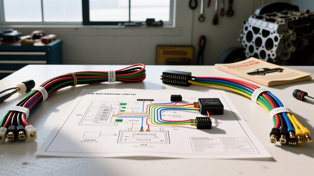
Introduction to the 1989 GMT400 Electrical Architecture
When diagnosing the legendary GMT400 platform, accessing an accurate 1989 Chevy truck wiring diagram is only the first step. The 1989 model year represents a critical transition period for Chevrolet C/K trucks, introducing the GMT400 chassis alongside the newer Throttle Body Injection (TBI) engine management systems. Unlike modern CAN-bus networks, the 1989 5.7L (350ci) TBI system relies on hardwired analog voltage signals, discrete pulse-width modulation (PWM) grounds, and a centralized Delco 1228747 Engine Control Module (ECM). Understanding this architecture requires moving beyond simple continuity testing and diving into voltage drop analysis, shared 5V reference circuit behavior, and precise pinout verification.
This advanced technical deep dive will dissect the critical circuits of the 1989 Chevy truck wiring diagram, focusing on the ECM power matrix, TBI sensor diagnostics, the High Energy Ignition (HEI) Electronic Spark Timing (EST) handshake, and the unique fuel pump oil-pressure bypass circuit that has saved countless drivers from being stranded.
ECM Power, Memory, and Ground Circuits
The heart of the 1989 TBI system is the Delco ECM, typically housed under the dash or behind the glovebox depending on the exact cab configuration. A common failure mode misdiagnosed as a 'dead ECM' is actually a voltage drop on the primary ground circuits. The ECM relies on heavy-gauge grounds to handle the high-current injector driver sinks. According to the SAE J1128 standard for low-tension primary wire, the ground circuits must maintain minimal resistance to prevent logic faults in the PROM (Programmable Read-Only Memory).
Table 1: Critical ECM Power and Ground Pinouts (1228747)
| Circuit ID | Wire Color | AWG Size | Function & Diagnostic Notes |
|---|---|---|---|
| 440 | Orange | 16 AWG | Constant Battery (Keep-Alive Memory). Must read within 0.1V of battery positive at all times. |
| 439 | Pink/Black | 16 AWG | Switched Ignition (Run/Start). Powers the internal ECM logic board and 5V voltage regulator. |
| 450 | Black/White | 14 AWG | Primary ECM Ground. Routes to the engine block. Voltage drop must be < 0.05V under load. |
| 450 | Black/White | 14 AWG | Secondary ECM Ground. Routes to the cylinder head or chassis ground bus. |
Expert Tip: Never use a test light to probe the ECM ground pins. The low current draw of an LED test light will not reveal high-resistance corrosion. Use a Digital Multimeter (DMM) set to DC Volts, placing the red lead on the battery positive and the black lead on the ECM ground pin while the engine is cranking.
Throttle Body Injection (TBI) and 5V Reference Diagnostics
The 1989 Chevy 5.7L utilizes a dual-injector TBI unit. The injectors are fed constant 12V via a Pink/Black wire (Circuit 120) from the fuel pump relay/oil pressure switch circuit. The ECM completes the circuit by pulsing the ground path (Light Blue for Injector 1, Light Green for Injector 2) using internal saturated-switch drivers.
However, the most complex diagnostic challenges arise in the shared 5V reference circuit (Circuit 532, Gray wire). This single Gray wire feeds the Throttle Position Sensor (TPS), the Manifold Absolute Pressure (MAP) sensor, and occasionally the EGR diagnostic switch. Because these sensors share a common 5V source generated by the ECM's internal voltage regulator, a dead short to ground in any of these sensors will pull the entire 5V reference down to 0V.
Sensor Pinout and Signal Tracing
- TPS (Throttle Position Sensor): Circuit 532 (Gray, 5V Ref), Circuit 416 (Dark Blue, Signal), Circuit 452 (Black, Ground). At closed throttle, the Dark Blue signal wire should read 0.50V - 0.54V. A reading above 0.60V will trigger a Code 21 (High TPS Voltage) and prevent the ECM from entering closed-loop fuel trim.
- MAP (Manifold Absolute Pressure): Circuit 532 (Gray, 5V Ref), Circuit 432 (Light Green, Signal), Circuit 452 (Black, Ground). At sea level with Key-On-Engine-Off (KOEO), the Light Green wire should read approximately 4.6V to 4.9V. At idle (high vacuum), it should drop to 1.0V - 1.5V.
If your 1989 Chevy truck cranks but will not start, and you measure 0V on the Gray wire at the TPS, do not immediately condemn the ECM. Disconnect the MAP sensor and the TPS sensor one by one. If the 5V reference returns when a specific sensor is unplugged, you have found your shorted component. For deeper diagnostic procedures on shared reference circuits, refer to Haynes technical tutorials on OBD-I analog sensor diagnostics.
HEI Ignition and Electronic Spark Timing (EST)
The 1989 GMT400 utilizes a large-cap HEI distributor with an internal 4-pin ignition module. The wiring diagram for this system shows a critical 'handshake' between the HEI module and the ECM known as Electronic Spark Timing (EST). When the engine is cranking (below 400 RPM), the HEI module controls base ignition timing using its internal pickup coil. Once the ECM detects RPMs above 400, it sends a 5V logic signal through the Bypass Circuit (Circuit 424, Tan/Black wire) to the HEI module. This tells the module to hand over timing control to the ECM. The ECM then pulses the EST Circuit (Circuit 423, White wire) to fire the coil.
Real-World Failure Mode: If the Tan/Black bypass wire is broken or has high resistance, the HEI module never receives the 5V handover signal. The truck will start and run, but it will be locked in base timing mode, resulting in severe hesitation, poor fuel economy, and a Check Engine Light (Code 42). Always verify the presence of the 5V bypass signal at the distributor connector using a DMM while the engine is running above 600 RPM.
The Fuel Pump Relay and Oil Pressure Bypass Circuit
One of the most ingenious—and frequently misunderstood—circuits in the 1989 Chevy truck wiring diagram is the dual-path fuel pump power feed. The ECM controls the fuel pump relay via Circuit 465 (Gray wire). When you turn the key to 'Run', the ECM energizes the relay for exactly 2 seconds to prime the TBI. If the ECM does not see distributor reference pulses (engine cranking), it shuts the relay off to prevent fuel spray in the event of an accident.
However, GM engineers included a mechanical oil pressure switch wired in parallel with the fuel pump relay. Once the engine cranks and oil pressure builds to roughly 4-7 PSI, the mechanical switch closes, sending direct battery voltage down the same Gray wire to the fuel pump. Diagnostic Insight: If your fuel pump relay fails, or the ECM loses its ground and cannot trigger the relay, the truck will crank for an extended period (waiting for oil pressure to build), and then suddenly start and run perfectly. If a customer complains of 'long cranking times before starting,' test the fuel pump relay circuit before replacing the fuel pump.
ALDL Connector Pinout and Diagnostic Procedures
Before OBD-II standardization, GM utilized the Assembly Line Diagnostic Link (ALDL), a 12-pin rectangular connector located under the driver's side dash. Understanding the 1989 ALDL pinout is mandatory for extracting flash codes and viewing live serial data using vintage scan tools or modern Arduino-based OBD-I readers.
Table 2: 1989 GM 12-Pin ALDL Connector Matrix
| Pin | Wire Color | Function |
|---|---|---|
| A | Black/White | Chassis Ground (Used for jumping to Pin B) |
| B | Tan/Black | Diagnostic Data / Flash Code Trigger |
| C | N/A | Not Used |
| D | Brown/White | Serial Data Output (8192 Baud for scan tools) |
| E | Black | Sensor Ground Reference |
| F | Tan | Tachometer Signal Output |
| G | Light Green | Fuel Pump Test / Prime Circuit |
| H | N/A | Not Used |
| J | N/A | Not Used |
| K | N/A | Not Used |
| L | N/A | Not Used |
| M | Purple/White | Check Engine Light / Field Service Mode Trigger |
To read manual flash codes, use a paperclip or jumper wire to bridge Pin A and Pin B with the Key On, Engine Off (KOEO). The Check Engine Light will flash Code 12 (one flash, pause, two flashes) three times to indicate the diagnostic system is functioning, followed by any stored fault codes. To enter 'Field Service Mode' (which displays closed-loop vs. open-loop status via the Check Engine Light while driving), bridge Pin A and Pin M instead.
Conclusion and Wiring Harness Preservation
The 1989 Chevy truck wiring diagram represents the pinnacle of analog, hardwired engine management. Because these vehicles are now over three decades old, the primary enemy of the TBI system is harness degradation. The insulation on the wires routed near the exhaust manifolds and the back of the cylinder heads (specifically the HEI and O2 sensor circuits) becomes brittle and flakes off, leading to intermittent shorts to ground that are notoriously difficult to trace. When repairing these circuits, always adhere to the ISO 6722 specification for automotive wire, utilizing cross-linked polyethylene (XLPE) insulated wire and sealed Deutsch or Weather-Pack connectors to ensure the electrical integrity of your GMT400 for decades to come.