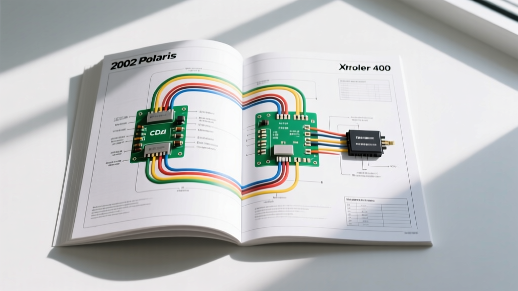
Electrical Architecture of the 2002 Polaris Xplorer 400
The 2002 Polaris Xplorer 400, powered by the 378cc Fuji single-cylinder two-stroke engine, relies on a robust but straightforward electrical architecture. Unlike modern fuel-injected UTVs, this platform utilizes a Capacitor Discharge Ignition (CDI) system paired with a dual-purpose stator. Understanding the wiring diagram 2002 polaris xplorer 400 circuit panel manual is critical for diagnosing parasitic draws, stator failures, and lighting circuit faults. This technical specification reference breaks down the OEM wire color codes, AWG sizing, and connector pinouts required for accurate bench-testing and field repairs.
Main Circuit Panel and Fuse Block Specifications
The primary power distribution node on the 2002 Xplorer 400 is located under the front storage pod, adjacent to the 12V 14Ah battery. The circuit panel integrates the main solenoid relay, the primary fuse block, and the DC headlight relay. According to SAE J1128 standards for low-tension automotive wiring, the main battery feeds utilize 10 AWG stranded copper wire to handle the peak cranking amperage (up to 190 CCA) without excessive voltage drop.
Fuse Panel Pinout and Rating Chart
When referencing the factory service manual, the fuse block utilizes standard ATO blade fuses. Corrosion in the unsealed pod environment is a common failure mode. Always check for continuity across the fuse blades and verify 12.6V at the load-side terminal with the ignition in the "ON" position.
| Circuit Designation | Fuse Rating | Wire Color (Source) | Wire Color (Load) | AWG |
|---|---|---|---|---|
| Main Ignition | 20A | Red | Red/White | 12 |
| Headlight (DC) | 15A | Red | Yellow | 14 |
| Tail/Brake Light | 10A | Red | Brown | 16 |
| Accessory (Winch) | 30A | Red | Black/White | 10 |
| Instrument Cluster | 5A | Red | Orange | 18 |
Stator, Regulator/Rectifier, and Charging Circuit
The Fuji 400 stator generates raw AC voltage which is rectified to DC to charge the battery and power the DC lighting circuits. The stator features a 3-phase lighting coil and a dedicated single-phase exciter coil for the CDI. The Regulator/Rectifier (R/R) unit is a 5-pin sealed module mounted to the frame near the rear fender to utilize ambient airflow for cooling.
OEM Wire Color Codes and R/R Pinout
Testing the stator requires unplugging the 3-phase connector and measuring AC voltage and resistance. Per the Clymer Polaris ATV Service Manual, the 3-phase output should yield balanced AC voltage (typically 28V-45V AC at 3000 RPM) across all three Yellow wire combinations.
| R/R Pin | Wire Color | Function | Specification / Test Value |
|---|---|---|---|
| 1 | Yellow | Stator Phase A | 0.2 - 0.5 Ohms to Phase B/C |
| 2 | Yellow | Stator Phase B | 0.2 - 0.5 Ohms to Phase A/C |
| 3 | Yellow | Stator Phase C | 0.2 - 0.5 Ohms to Phase A/B |
| 4 | Red | DC Output (+12V) | 13.8V - 14.4V DC at 3000 RPM |
| 5 | Black | Ground (-) | Continuity to chassis (< 0.1 Ohms) |
Capacitor Discharge Ignition (CDI) and Kill Circuit
The 2002 Xplorer 400 uses a CDI module (Polaris P/N 4110182 or equivalent) to manage ignition timing. The CDI receives a high-voltage pulse from the stator's exciter coil and discharges it into the primary winding of the ignition coil. The kill switch circuit operates on a "ground-to-kill" logic. When the tether or handlebar kill switch is engaged, it grounds the White/Red wire, dumping the CDI's stored energy to the chassis and preventing the spark plug from firing.
Ignition Coil Resistance Specifications
If the engine cranks but produces no spark, the ignition coil must be bench-tested using a digital multimeter. Disconnect the primary leads and the high-tension spark plug cap.
- Primary Resistance: 0.30 - 0.50 Ohms (measured between the primary terminal and the mounting ground).
- Secondary Resistance: 3,000 - 5,000 Ohms (measured between the primary terminal and the spark plug cap terminal). Note: If the cap contains an internal resistor, expect an additional 5,000 Ohms.
- CDI Exciter Input: 120 - 180 Ohms (measured at the stator Red/White wire to ground).
Lighting Circuit Diagnostics and Grounding
The 2002 Xplorer 400 utilizes a DC-powered headlight system, meaning the headlight will illuminate with the key in the "ON" position, even if the engine is not running. This differs from older AC-stator systems. The headlight circuit routes from the 15A fuse block, through the handlebar dimmer switch (High/Low beam), and terminates at the 35W/35W H4 halogen bulb.
A common failure mode is the melting of the H4 bulb connector due to high resistance in the ground path. The headlight ground (Black wire) shares a common ground point on the steering stem with the instrument cluster. If this ground point corrodes, the headlight current will backfeed through the instrument cluster ground, causing the speedometer backlight to dim or pulse when the high beam is engaged. To resolve this, clean the common ground node with a wire brush, apply an anti-oxidant compound, and verify continuity to the battery negative terminal. If the H4 connector shows signs of thermal deformation, splice in a heavy-duty ceramic H4 pigtail using 14 AWG wire and adhesive-lined heat shrink tubing to ensure a weather-tight seal.
No-Spark Troubleshooting Decision Tree
Electrical faults on the Xplorer 400 frequently stem from vibration-induced wire chafing near the steering stem or corrosion inside the unsealed AMP connectors. Follow this diagnostic sequence before replacing expensive CDI units:
- Verify Battery Voltage: Ensure the battery reads at least 12.4V DC. A weak battery will crank the engine but fail to provide the minimum threshold voltage required for the CDI to trigger.
- Isolate the Kill Circuit: Unplug the handlebar kill switch and tether lanyard connectors. If spark returns, the fault is a shorted switch or a pinched White/Red wire in the steering column harness.
- Test Stator Exciter Coil: Measure resistance between the Red/White stator wire and engine ground. An open loop (OL) indicates a broken internal stator winding, requiring a complete stator replacement.
- Inspect Ignition Coil Ground: The ignition coil mounts to the frame. Remove the mounting bolt, clean the chassis contact patch down to bare metal, and re-torque to 12 ft-lbs. A poor ground will prevent the secondary circuit from completing.
Winch and Accessory Panel Wiring Integration
Many 2002 Xplorer 400 models were equipped with the Polaris Glacier or KFI winch packages. The circuit panel manual dictates that the winch contactor solenoid must be wired directly to the battery positive terminal via a 6 AWG stranded cable, bypassing the main fuse block to prevent overloading the OEM harness. The control switch circuit draws minimal amperage and should be protected by an inline 10A ATO fuse, tapping into the Orange accessory wire at the ignition switch connector.
The standard 5-pin Bosch-style relay used for the winch control circuit follows standard automotive pinouts: Pin 30 (Battery +), Pin 87 (To Contactor Coil), Pin 85 (Ground), Pin 86 (Switched 12V from Dash Button), and Pin 87a (Unused). Using a relay prevents the high current of the contactor coil from burning out the delicate contacts inside the OEM Polaris rocker switch.
For comprehensive schematics and torque specifications for all electrical fasteners, technicians should cross-reference the official Polaris OEM Parts and Service Documentation. Proper dielectric grease application on all 3.5mm pitch sealed connectors is mandatory to prevent the ingress of moisture, which is the leading cause of parasitic battery drain on stored ATVs.