Introduction: The Hidden Dangers of Auxiliary Switch Panels
Whether you are outfitting a Jeep Wrangler JL, a Ford Bronco, or a heavy-duty commercial truck, adding auxiliary accessories requires a robust power distribution system. A standard 3-gang switch panel is the most popular choice for managing a roof-mounted LED light bar, an onboard air compressor, and a winch solenoid. However, misinterpreting a diagram of 3 gang switch wiring is one of the leading causes of aftermarket electrical fires, melted harnesses, and parasitic battery drains. In the automotive electrical field, assuming that a switch can handle the direct load of high-draw accessories is a catastrophic error. This guide breaks down the critical mistakes DIYers and novice technicians make when installing auxiliary 3-gang panels and provides the safety warnings necessary to keep your vehicle's electrical system intact.
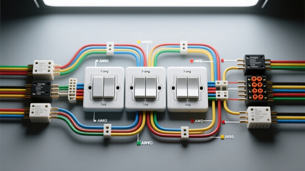
Understanding the True Diagram of 3 Gang Switch Wiring
Most commercial 3-gang panels do not route main load current through the dashboard switch. Instead, they utilize a relay-driven architecture. When reviewing a standard diagram of 3 gang switch wiring, the most critical element to understand is the separation of the high-amperage load circuit from the low-amperage trigger circuit. The switches on your dash merely complete a low-current ground or 12V+ trigger path that activates an electromagnetic coil inside a relay. The relay then acts as a heavy-duty gatekeeper, allowing battery power to flow directly to the accessory.
The Standard ISO Mini Relay Pinout
To safely wire a 3-gang panel, you must understand the standard Bosch-style ISO mini relay pinout. Miswiring these pins will result in immediate short circuits or switched grounds.
- Pin 30: 12V+ Battery Input (High Amperage, typically 10-12 AWG)
- Pin 87: Output to Load / Accessory (High Amperage, typically 10-12 AWG)
- Pin 86: 12V+ Trigger from Dash Switch (Low Amperage, 18 AWG)
- Pin 85: Ground for Relay Coil (Low Amperage, 18 AWG)
Critical Mistakes When Wiring a 3-Gang Panel
Mistake 1: Bypassing the Relay (The Direct-Wire Fallacy)
The most dangerous mistake occurs when an installer looks at a simplified diagram and attempts to wire the load directly through the dashboard switch to save time. Standard automotive rocker switches are typically rated for 10A to 20A maximum. While an LED light bar might only pull 12A, an onboard air compressor or a winch solenoid can experience inrush currents exceeding 40A upon startup. Routing this current directly through the switch will overwhelm the internal copper contacts, causing them to arc, weld together, and eventually melt the plastic switch housing, potentially igniting the dashboard.
Mistake 2: Undersizing the Ground Wire and Poor Chassis Prep
According to SAE J1128 standards, the ground wire in a DC circuit must be of equal or greater gauge (thickness) than the positive supply wire. A common error is using 12 AWG for the positive feed but dropping down to 16 AWG for the ground to save money. Furthermore, attaching the ground ring terminal to painted metal or using a standard flat washer instead of a star washer prevents a solid chassis ground. This introduces resistance, causing voltage drop, dimming lights, and excessive heat generation at the grounding point. Always sand down to bare metal and use an adhesive-lined heat shrink ring terminal.
Mistake 3: Daisy-Chaining Power Sources and Ignoring Voltage Drop
Running a single 12 AWG wire from the battery to a distribution block, and then splitting it to feed three separate 30A relays, is a recipe for a voltage drop disaster. If all three accessories (e.g., lights, compressor, and auxiliary fan) are turned on simultaneously, the main feed wire will be subjected to 90A+ of current. A 12 AWG wire is only rated for roughly 20A-25A in a chassis wiring application. The wire will act as a resistor, generating immense heat and causing a severe voltage drop that can damage sensitive electronics or trigger a fire. The main feed to a 3-gang relay block must be sized for the cumulative maximum load, typically requiring 8 AWG or 6 AWG wire with a high-amperage ANL fuse or marine-grade circuit breaker at the battery terminal.
Wire Gauge and Fuse Specification Chart
Use the following reference chart to ensure your 3-gang switch panel is wired with the correct AWG sizes and overcurrent protection. Data based on standard automotive GXL/TXL cross-linked wire specifications for engine bay routing.
| Accessory Load Type | Avg Amperage | Wire Gauge (AWG) | Overcurrent Protection |
|---|---|---|---|
| LED Light Bar (40-inch) | 15A - 18A | 14 AWG | 20A ATO Blade Fuse |
| Onboard Air Compressor | 25A - 30A | 10 AWG | 40A Circuit Breaker |
| Winch Contactor Solenoid | 40A+ (Inrush) | 8 AWG | 80A Marine Circuit Breaker |
| Switch Trigger Wire (Coil) | < 1A | 18 AWG | 5A Inline Glass Fuse |
| Main Battery Feed (3-Gang) | Cumulative | 6 AWG or 8 AWG | 100A ANL Fuse |
Troubleshooting a Faulty 3-Gang Installation
When an accessory fails to activate, do not immediately replace the switch. Follow this diagnostic decision tree to isolate the fault safely:
- Step 1: Check the Main Feed. Use a digital multimeter (DMM) to test voltage at Pin 30 of the relay. You should read 12.2V to 12.6V (engine off). If voltage is low or zero, trace back to the main battery fuse and distribution block.
- Step 2: Test the Trigger Circuit. Press the dash switch and probe Pin 86. If you read 12V+ here, the dash switch and trigger wiring are functioning correctly. If you read 0V, the issue is a blown inline trigger fuse or a broken 18 AWG wire behind the dash.
- Step 3: Verify the Relay Coil Ground. Check continuity between Pin 85 and the vehicle chassis. A reading of OL (Open Loop) indicates a failed ground connection at the chassis ring terminal.
- Step 4: Bypass the Relay (Load Test). With the vehicle off, use a heavy-duty jumper wire to bridge Pin 30 and Pin 87 directly. If the accessory turns on, the relay is faulty or the wiring from Pin 87 to the accessory is broken. If the accessory remains dead, the fault lies in the accessory itself or its local ground.
Safety Warnings: Inductive Loads and Wire Insulation
When wiring inductive loads like winch solenoids or air compressors through a 3-gang panel, you must account for inductive kickback. When the relay opens, the collapsing magnetic field generates a high-voltage spike that can arc across the relay contacts or backfeed into the vehicle's ECU/PCM, causing computer damage. Always install a flyback diode or a transient voltage suppressor (TVS) across the relay coil (Pins 85 and 86) or the load terminals to absorb these spikes.
Additionally, never use standard PVC-insulated wire in the engine bay. As noted by resources like AA1Car's electrical diagnostics guide, engine bay temperatures can easily exceed the melting point of PVC. Always specify GXL or TXL wire, which features cross-linked polyethylene insulation rated for continuous exposure up to 125°C (257°F). Finally, avoid soldering wire connections in high-vibration off-road environments. Solder wicks into the wire strands, creating a rigid, brittle point that will eventually snap under chassis flex. Instead, use a high-quality ratcheting crimper and adhesive-lined polyolefin heat shrink terminals to ensure a gas-tight, vibration-proof connection.
Conclusion
A properly executed diagram of 3 gang switch wiring transforms a vehicle into a capable, multi-functional machine. However, cutting corners on wire gauge, ignoring relay pinouts, or failing to secure proper chassis grounds will turn your auxiliary panel into a severe fire hazard. By respecting amperage limits, utilizing circuit breakers for inductive loads, and adhering to SAE wire standards, you ensure that your off-road or commercial rig remains safe, reliable, and ready for any environment.