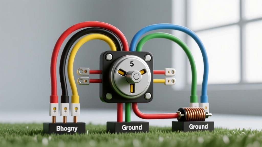
Introduction to the 5-Prong Ignition System
When your riding mower refuses to crank or the engine won't shut off, the ignition switch is often the prime suspect. The 5 prong lawn mower ignition switch wiring diagram is the most common electrical configuration found in modern garden tractors and riding mowers, including popular models from Craftsman, MTD, Husqvarna, and John Deere. Unlike automotive ignition switches that manage complex CAN-bus networks and transponder keys, lawn mower switches rely on a straightforward, robust, and easily testable analog circuit.
For beginners, looking at a mess of faded, dirt-caked wires behind the dashboard can be overwhelming. However, by understanding the fundamental purpose of each of the five terminals, you can diagnose, replace, and rewire your mower's ignition system with confidence. This guide breaks down the exact pinouts, wire gauge requirements, and safety interlock logic necessary to get your tractor running safely and reliably.
Decoding the 5 Terminals: B, S, I, M, and G
The universal standard for small engine 5-prong switches uses letter designations stamped directly onto the metal casing or the plastic connector block. Relying on wire colors is a common beginner mistake; OEM manufacturers frequently change wire insulation colors depending on the model year and assembly plant. Always wire according to the terminal letters.
- B (Battery): This is the primary 12V DC input. It receives constant power directly from the battery or the main harness junction block. It is typically protected by a 15A or 20A inline fuse.
- S (Starter): This terminal sends 12V to the starter solenoid's trigger wire when the key is turned to the START position. In modern mowers, this wire routes through a series of safety interlock switches before reaching the solenoid.
- I (Ignition / Accessory): This terminal provides 12V power to the ignition coil (on battery-ignition models), the fuel shutoff solenoid on the carburetor, and dashboard accessories. It is active in both the RUN and START positions.
- M (Magneto): This is the engine kill terminal. Most small engines use a magneto ignition system. To stop the engine, the M terminal provides a path to ground, shorting out the ignition coil and preventing it from generating a spark.
- G (Ground): This terminal connects to the mower's chassis ground. It works in tandem with the M terminal to kill the engine when the key is in the OFF position.
Terminal Pinout and Switch Position Matrix
Understanding which terminals connect internally during each key position is critical for bench-testing a new switch before installation. Below is the standard continuity matrix for a 5-prong magneto-kill ignition switch.
| Key Position | B (Battery) | S (Starter) | I (Ignition) | M (Magneto) | G (Ground) |
|---|---|---|---|---|---|
| OFF | Open | Open | Open | Closed to G | Closed to M |
| RUN | Closed to I | Open | Closed to B | Open | Open |
| START | Closed to I & S | Closed to B | Closed to B | Open | Open |
The Safety Interlock System: Why Your Mower Won't Crank
The most common reason a beginner's wiring job fails is ignoring the safety interlock circuit. The S (Starter) terminal rarely sends power directly to the starter solenoid. Instead, the wire from the S terminal acts as a trigger that must pass through a series of normally-open (NO) or normally-closed (NC) safety switches.
Typically, the S terminal wire routes to the Brake Pedal Switch. If the brake is not depressed, the circuit remains open, and the starter will not engage. From the brake switch, the wire may route to the PTO (Power Take-Off) Switch. If the mower deck is engaged (PTO pulled out), the circuit to the starter solenoid is broken to prevent the engine from cranking while the blades are in gear. Finally, some models include a Seat Switch bypass. When troubleshooting a no-crank condition, always use a digital multimeter to verify continuity through these safety switches before condemning the ignition switch.
Step-by-Step Wiring and Crimping Best Practices
Lawn mowers operate in high-vibration, high-moisture environments. A sloppy wiring job will fail within a single mowing season. Follow these professional automotive electrical standards to ensure longevity:
- Disconnect the Battery: Always remove the negative (-) battery cable first to prevent accidental short circuits and sparks near the fuel system.
- Select the Correct Wire Gauge: According to the SAE J1128 Low Tension Primary Cable Standard, the B and S terminals should utilize 12 AWG stranded copper wire to handle the inrush current of the starter solenoid and prevent voltage drop. The I, M, and G terminals can safely use 14 AWG or 16 AWG wire, as they carry minimal amperage.
- Use Fully Insulated Spades: The standard connector for a 5-prong mower switch is the 0.250-inch (1/4") female quick-disconnect spade. Always use fully insulated nylon or vinyl spades to prevent the metal housing from shorting against the mower's steel dashboard.
- Ratcheting Crimpers are Mandatory: Never use cheap plier-style crimpers. Use a ratcheting crimping tool designed for insulated terminals. A ratcheting crimper applies uniform pressure, creating a gas-tight connection that will not vibrate loose. For added protection against moisture and corrosion, slide a piece of adhesive-lined heat shrink tubing over the wire before crimping, and shrink it over the terminal barrel.
- Apply Dielectric Grease: Before pushing the spade connectors onto the switch prongs, apply a small dab of silicone dielectric grease. This displaces moisture and prevents galvanic corrosion, which is the leading cause of voltage drop in small engine electrical systems.
Bench Testing Your Switch with a Multimeter
Before routing wires through the mower's chassis, always bench-test the replacement switch. Even brand-new switches from reputable suppliers can suffer from internal contact defects. Set your digital multimeter to the Continuity (beep) or Ohms (Ω) setting.
Insert the probes into the corresponding terminal wire holes or touch the metal prongs. In the OFF position, your meter should beep only when touching M and G. In the RUN position, it should beep only when touching B and I. In the START position, it should beep when touching B to I, and B to S. If any position shows an open circuit where a closed circuit is expected, return the switch immediately.
Troubleshooting Common Electrical Gremlins
Even with a perfect wiring diagram, real-world troubleshooting requires a logical approach. Here are the most frequent failure modes associated with the 5-prong ignition setup:
Symptom: The Engine Runs, But Won't Shut Off When the Key is Removed
The Cause: The Magneto kill circuit is failing to ground. When the key is turned to OFF, the M and G terminals are supposed to bridge, grounding the ignition coil's primary winding and killing the spark.
The Fix: Check the wire connected to the M terminal. Trace it back to the engine block and verify it is securely connected to the ignition coil's kill tab. Ensure the G terminal has a solid, rust-free connection to the mower's chassis. If the switch casing itself is plastic and relies on the G terminal wire for grounding, a broken G wire will result in a run-on engine.
Symptom: The Dashboard Lights Up, But the Starter Solenoid Doesn't Click
The Cause: Power is successfully leaving the B terminal and reaching the I terminal (proving the switch's internal B-I contacts are good), but the START position is failing to send power to the S terminal, or the safety interlock circuit is open.
The Fix: Have an assistant turn the key to START while you probe the S terminal with a multimeter. If you read 12V at the S terminal, the ignition switch is perfectly fine. The fault lies downstream in the brake switch, PTO switch, or the solenoid trigger wire itself. If you read 0V at the S terminal during the START position, the internal copper wiper inside the ignition switch is worn out and the unit must be replaced.
Authoritative References and Further Reading
For advanced diagnostics, OEM service manuals, and detailed small engine electrical theory, consult the following industry-standard resources:
- SAE International - J1128 Low Tension Primary Cable Standard (Guidelines for wire gauge selection and insulation types in automotive and small engine applications).
- Jack's Small Engines - Ignition Switch Testing and Replacement Guide (Excellent visual references for OEM switch variations and multimeter testing procedures).
By respecting the terminal designations, adhering to proper AWG sizing, and understanding the safety interlock logic, you can confidently conquer any 5-prong ignition switch repair. Proper electrical maintenance ensures your mower starts on the first turn every time and shuts down safely when the job is done.