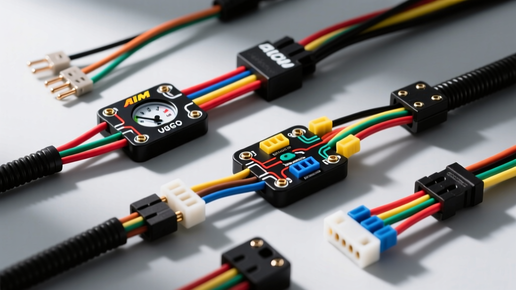
Choosing Between AEM UEGO and X-Series Widebands
When integrating a wideband oxygen sensor into a performance vehicle, selecting the right controller and understanding its specific wiring diagram is critical for accurate air-fuel ratio (AFR) data logging and engine safety. AEM Electronics has dominated this space with two primary generations of wideband controllers: the legacy UEGO (PN 30-4110) and the modern X-Series (PN 30-0300). While both utilize the highly reliable Bosch 4.9 LSU wideband sensor, their internal architectures, harness configurations, and output protocols differ significantly. This guide provides an in-depth comparison of the AEM air fuel ratio gauge wiring diagrams for both units, detailing pinouts, AWG requirements, and real-world troubleshooting to help you select and wire the correct system for your standalone ECU or factory harness integration.
Legacy AEM UEGO (PN 30-4110) Wiring Diagram & Pinout
The AEM UEGO was the industry standard for over a decade. Its wiring diagram is relatively simple, relying heavily on analog voltage outputs and a serial data stream. The most critical physical difference in the UEGO harness is the inclusion of an inline calibration resistor. Because the legacy controller required manual calibration to the specific sensor's diffusion characteristics, this resistor is factory-matched to the sensor. If you must extend the UEGO harness, the calibration resistor must remain within 18 inches of the controller plug to prevent signal degradation and calibration drift.
UEGO Controller 6-Pin Harness Pinout
| Pin | Wire Color | Function | Recommended AWG | Technical Notes |
|---|---|---|---|---|
| 1 | Red | 12V Switched Ignition | 14 AWG | Must handle 2.5A+ during sensor heater startup. |
| 2 | Black | Chassis / Power Ground | 14 AWG | Ground directly to battery negative or clean block ground. |
| 3 | White | Analog Out (0-5V) | 22 AWG Shielded | Linear output for aftermarket ECUs (0V=10.0 AFR, 5V=17.0 AFR). |
| 4 | Brown | Analog Out (0-1V) | 22 AWG | Narrowband simulator output for older factory ECUs. |
| 5 | Yellow | Serial Data Out (RS232) | 22 AWG | Used for legacy AEM data loggers; incompatible with modern CAN. |
| 6 | N/A | Empty / Not Connected | N/A | Reserved for factory testing. |
AEM X-Series (PN 30-0300) Wiring Diagram & Pinout
The AEM X-Series represents a massive leap in wideband technology. Utilizing X-Digital technology, the X-Series eliminates the need for the inline calibration resistor by reading the sensor's unique laser-etched calibration data directly from the Bosch 4.9 LSU chip. Furthermore, the X-Series harness introduces native CAN-bus support, making it the superior choice for modern standalone ECUs like Haltech, MoTeC, and Link. The wiring diagram for the X-Series utilizes an 8-pin sealed connector, providing dedicated CAN-High and CAN-Low circuits.
X-Series 8-Pin Harness Pinout
| Pin | Wire Color | Function | Recommended AWG | Technical Notes |
|---|---|---|---|---|
| 1 | Red | 12V Switched Ignition | 14 AWG | Relay-driven from battery; do not use ECU 5V reference. |
| 2 | Black | Power Ground | 14 AWG | Critical for Nernst cell accuracy; avoid painted chassis grounds. |
| 3 | White | Analog Out (0-5V) | 22 AWG Shielded | Programmable via gauge face; default 0V=10.0, 5V=17.0 AFR. |
| 4 | Yellow | CAN-High | 22 AWG Twisted | SAE J1939 / CAN 2.0B compatible. Requires 120-ohm termination. |
| 5 | Green | CAN-Low | 22 AWG Twisted | Twist with Yellow wire to reject electromagnetic interference. |
| 6 | Blue | Serial Data (RS232) | 22 AWG | Legacy logging support. |
| 7 | Orange | Dimmer / 12V Lighting | 18 AWG | Connect to headlight switch for automatic gauge dimming. |
| 8 | Purple | Program / Config | 22 AWG | Used for PC configuration via AEM software. |
Selection Guide: Which AEM Harness Fits Your Build?
Choosing between the UEGO and X-Series depends entirely on your ECU architecture and data logging requirements. Below is a comparison matrix to guide your selection based on wiring complexity and protocol support.
| Feature | AEM UEGO (Legacy) | AEM X-Series (Modern) |
|---|---|---|
| ECU Compatibility | MegaSquirt, older factory ECUs | Haltech, MoTeC, Link, Holley, AEM Infinity |
| Data Protocol | Analog (0-5V) & RS232 Serial | CAN-Bus, Analog (0-5V), RS232 |
| Wiring Complexity | Low (4 active wires) | Medium (Requires CAN termination if daisy-chaining) |
| Calibration Resistor | Required (Inline on harness) | Not Required (Sensor auto-calibrates) |
| Sensor Extension | Difficult (Must move resistor) | Easy (Standard Bosch 4.9 extensions work) |
Critical Wiring Practices & AWG Specifications
When executing the AEM air fuel ratio gauge wiring diagram, wire gauge and routing are just as important as the pinout. The Bosch 4.9 LSU sensor contains a pump cell, a Nernst (reference) cell, and an integrated heater. During cold starts, the ECU or controller must clear condensation from the sensor element by pulsing the heater circuit. This initial draw can exceed 2.5 Amps. If you wire the Red 12V Switched wire using standard 18 AWG or 20 AWG wire, the voltage drop across the wire will cause the controller to see less than 11V at startup, immediately triggering a 'Heater Circuit Fault' and displaying an 'ERR' code on the gauge. Always use a minimum of 14 AWG for the power and ground circuits, and trigger the power via an automotive 30A relay controlled by an ignition-switched source.
For the analog 0-5V output (White wire), routing is paramount. High-voltage ignition wires, MSD coils, and alternator stators emit massive electromagnetic interference (EMI). If the 0-5V analog wire runs parallel to spark plug wires, the ECU will read the EMI as voltage spikes, causing erratic fuel trims or false knock sensor readings. Always use shielded 22 AWG cable for the analog output, and ground the shield drain wire exclusively at the ECU end, leaving it floating at the AEM controller end to prevent ground loops.
Real-World Troubleshooting & Failure Modes
Even with a perfect wiring diagram, environmental factors and installation errors can skew AFR data. Use this decision tree to diagnose common AEM wideband wiring faults:
- Symptom: Gauge reads wildly rich (0.60 - 0.70 AFR) at idle and never recovers.
Cause: Ground Offset. The AEM controller measures the Nernst cell voltage relative to its own ground. If the AEM Black wire is grounded to the chassis, but the ECU is grounded to the engine block, the voltage differential between the block and chassis (often 0.1V to 0.3V under load) is interpreted as a massive drop in oxygen, reading as a rich condition.
Fix: Relocate the AEM Black ground wire to the exact same ground stud as the ECU's main power ground, or wire it directly to the battery negative terminal. - Symptom: Gauge displays 'ERR' or flashes after 30 seconds of key-on time.
Cause: Heater Circuit Voltage Drop or Bad Pin Crimp. The controller cannot achieve the target 750°C sensor temperature.
Fix: Check the 12V switched source with a multimeter during cranking. If voltage drops below 10.5V, move the relay trigger to a run-only circuit, and verify the 14 AWG Red wire has clean, solder-sealed crimps. - Symptom: CAN-Bus data drops out intermittently on Haltech/MoTeC ECU.
Cause: Missing 120-Ohm Termination Resistors. CAN-Bus requires a 120-ohm resistor at both physical ends of the network bus to prevent signal reflection.
Fix: If the AEM X-Series is the only device on the CAN network, ensure the ECU has its internal termination resistor enabled, or install a physical 120-ohm resistor across the Yellow (CAN-H) and Green (CAN-L) wires at the AEM harness plug.
Authoritative Technical References
For deeper integration into custom harnesses, consult the following engineering resources:
- AEM Electronics X-Series Wideband UEGO Controller Installation Manual - Official pinout configurations and CAN-bus ID mapping.
- Bosch Motorsport LSU 4.9 Sensor Datasheet - Nernst cell impedance specifications and heater circuit current draw profiles.
- SAE J1939 CAN-Bus Standards (SAE International) - Guidelines for twisted pair routing, shielding, and 120-ohm termination in automotive CAN networks.