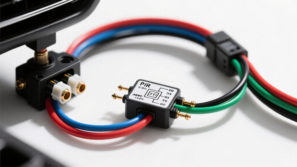
The Role of PIR Sensors in Modern Vehicle Architecture
Passive Infrared (PIR) sensors have evolved from basic residential security components into critical modules within advanced automotive electrical systems. In the automotive sector, PIR sensors are primarily deployed for two distinct applications: aftermarket volumetric intrusion detection (bypassing the limitations of shock and glass-break sensors) and OEM Cabin Occupancy Monitoring, including Child Presence Detection (CPD) mandated by recent Euro NCAP safety protocols. Unlike ultrasonic sensors that rely on sound wave reflection, PIR sensors detect rapid changes in infrared radiation caused by a warm body moving across the sensor's Fresnel lens field of view. This makes them highly effective for monitoring the interior cabin volume without triggering false alarms from external environmental noise, provided the wiring and thermal management are executed to exact automotive standards.
Core Architecture of Automotive PIR Modules
An automotive PIR module consists of a pyroelectric sensing element, a signal conditioning ASIC (Application-Specific Integrated Circuit), and a specialized Fresnel lens designed to map the interior geometry of a vehicle cabin. The ASIC filters out low-frequency thermal drift (such as the cabin heating up on a sunny day) and isolates the specific frequency band of human movement (typically 0.1 Hz to 10 Hz). Because the sensor operates in the harsh electrical and thermal environment of a vehicle, the wiring harness must be designed to mitigate electromagnetic interference (EMI) from the alternator, ignition coils, and CAN/LIN bus networks, while maintaining strict voltage tolerances.
Standard 4-Pin Aftermarket PIR Security Sensor Pinout
For high-end aftermarket security integrations (such as Compustar, Viper, or Directed Electronics systems), the volumetric PIR sensor typically utilizes a 4-pin JST SM or Molex connector. The wiring harness must utilize automotive-grade cross-linked polyethylene (TXL or GXL) wire to withstand under-dash temperature fluctuations and abrasion.
| Pin | Function | Standard Wire Color | AWG Size | Technical Notes |
|---|---|---|---|---|
| 1 | +12V Constant (KL30) | Red | 18 AWG | Requires inline 2A ATO fuse. Connect to constant battery source, not switched ignition, to maintain security while parked. |
| 2 | Chassis Ground (KL31) | Black | 18 AWG | Must be terminated to a clean, unpainted chassis ground point. Do not share ground with high-current audio amplifiers. |
| 3 | Trigger Out (Signal) | White | 22 AWG | Open-Collector NPN output. Pulls to ground upon motion detection. Requires pull-up resistor at the alarm brain. |
| 4 | Tamper / Anti-Mask | Yellow | 22 AWG | Normally Closed (NC) loop. Opens if the sensor housing is removed or physically shielded by an attacker. |
Open-Collector Signal Integration and Pull-Up Logic
The most common point of failure in aftermarket PIR sensor wiring is the mismanagement of the signal wire (Pin 3). Automotive PIR sensors utilize an Open-Collector NPN transistor output rather than a direct 12V positive pulse. This design is chosen for its noise immunity and compatibility with various alarm control module logic levels. When motion is detected, the NPN transistor saturates, pulling the signal line to ground (0V). When no motion is detected, the transistor is off, leaving the signal line "floating."
If this floating line is connected directly to a high-impedance alarm brain input without a pull-up resistor, it will act as an antenna, absorbing EMI from the vehicle's ignition system and causing phantom alarms. To wire this correctly, a 10kΩ 1/4W pull-up resistor must be soldered between the signal wire and the alarm module's +12V reference or +5V logic reference (consult the specific alarm brain schematic). This ensures the line rests at a stable HIGH state and is actively pulled LOW only when the PIR sensor triggers. For runs longer than 4 feet through the vehicle's A-pillar or dash harness, the signal wire should be routed as a twisted pair with the ground wire to reject common-mode noise.
OEM Cabin Occupancy and Child Presence Detection (CPD)
In modern OEM applications (e.g., BMW F/G-Series interior motion sensors or Hyundai/Kia CPD modules), the PIR sensor is no longer a simple switch. It is a smart node on the vehicle's LIN (Local Interconnect Network) or CAN bus. These sensors utilize 3-pin or 4-pin TE Connectivity MATEnet or H-MTD connectors. The pinout typically includes KL30 (12V), KL31 (Ground), and a LIN bus data line. The LIN bus allows the Body Domain Controller (BDC) to request specific diagnostic data from the PIR sensor, including thermal baseline calibration, lens obstruction status, and precise occupancy mapping. Wiring repairs on these OEM harnesses require specialized crimping tools and the use of shielded twisted-pair (STP) cable for the LIN bus line to prevent data corruption from adjacent high-current wiring.
Environmental Hardening and EMI Mitigation
Automotive electrical systems are governed by strict electromagnetic compatibility (EMC) standards, notably SAE J1113. The interior cabin is subjected to severe voltage transients, including load dump and inductive spikes from window motors and HVAC blower motors. To protect the sensitive pyroelectric element and ASIC, the PIR sensor's internal PCB includes TVS (Transient Voltage Suppression) diodes. However, the external wiring must also be hardened. Install a ferrite bead choke on the +12V and Ground lines within 3 inches of the sensor connector to suppress high-frequency alternator whine. Furthermore, the physical placement of the sensor is critical; it must never be mounted directly in the path of HVAC defroster vents. Rapid thermal convection currents from the AC or heater will overwhelm the sensor's thermal compensation algorithm, resulting in continuous false triggering.
Diagnostic Troubleshooting Matrix
When diagnosing a malfunctioning automotive PIR system, technicians must isolate whether the fault lies in the sensor's internal pyroelectric element, the wiring harness, or the control module's logic configuration.
| Symptom | Probable Root Cause | Diagnostic Action & Fix |
|---|---|---|
| Phantom alarms trigger randomly while parked. | Floating signal line picking up EMI, or HVAC thermal draft. | Verify 10kΩ pull-up resistor is installed on the trigger wire. Check sensor placement relative to dash vents. |
| Sensor fails to trigger during walk-test. | Voltage drop on +12V line below 10.5V, or faulty Fresnel lens. | Measure voltage at Pin 1 during cranking. Ensure 18 AWG wire is used and connections are soldered, not T-tapped. |
| Alarm triggers immediately upon arming. | Tamper loop (Pin 4) open circuit or misconfigured NC/NO logic. | Check continuity of Yellow wire. Verify alarm brain is set to Normally Closed for the tamper/24-hour zone input. |
| OEM LIN Bus U-Code (Communication Fault) | Shielding breach on LIN wire or water ingress in MATEnet connector. | Oscilloscope LIN bus waveform. Check for 12V square wave. Inspect connector for green corrosion. |
Wire Routing and Installation Best Practices
When routing the PIR sensor harness through the vehicle's headliner or A-pillar, always adhere to the environmental testing guidelines outlined in ISO 16750-2 for electrical loads. Avoid running the sensor's low-voltage signal wires parallel to high-current amplifier power cables or ignition coil feeds. If crossing high-current wires is unavoidable, do so at a strict 90-degree angle to minimize inductive coupling. Use automotive-grade Tesa tape (fleece or PVC harness tape) to secure the wiring to the OEM headliner bracing, ensuring the harness does not rattle against the roof panel, as micro-vibrations can occasionally induce piezoelectric noise in poorly shielded sensor modules.
Authoritative References
- SAE J1113: Electromagnetic Compatibility Measurement Procedures and Limits for Components - Essential for understanding EMI shielding requirements in automotive sensor wiring.
- ISO 16750-2: Road vehicles — Environmental conditions and testing - Governs the electrical load and voltage drop tolerances for automotive electronic modules.
- Texas Instruments Application Note: Sensor Interfacing and Open-Collector Logic - Provides the foundational electrical engineering principles for pull-up resistor calculations and NPN transistor outputs.