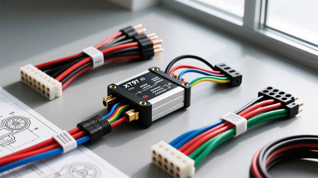
The EV Connection: Why E-Bike Wiring Demands Automotive Standards
When transitioning from traditional automotive electrical systems to Light Electric Vehicles (LEVs), many builders underestimate the complexity of high-current, low-voltage DC architectures. Finding the correct wiring diagram for electric bike builds is not just about connecting a battery to a motor; it requires a deep understanding of Pulse Width Modulation (PWM) frequencies, Hall effect sensor logic, and high-amperage thermal management. An e-bike operating at 52V and 40A continuous draws nearly 2,080 watts, generating significant heat at connection points if wire gauge and crimp standards are ignored.
In the automotive world, we rely on SAE J1128 standards for low-tension primary cables and strict Deutsch connector protocols. E-bikes demand the same rigor. This guide compares the three dominant controller ecosystems—Bafang, Kelly, and Generic Square-Wave—and provides a comprehensive selection matrix to help you choose the right schematic, wire gauge, and connector topology for your specific build.
Controller Ecosystem Comparison
Selecting a wiring schematic begins with understanding the proprietary versus open-source nature of the controller you are deploying. Each manufacturer approaches pinouts, waterproofing, and communication protocols differently.
Bafang Mid-Drive Systems (BBSHD / BBS02)
Bafang utilizes a highly proprietary, closed-loop wiring architecture. If you are pulling a wiring diagram for electric bike builds using a BBSHD, you will immediately notice the reliance on Higo (formerly Julet) waterproof connectors. These are excellent for weather resistance but notoriously difficult to repair in the field without proprietary crimping tools.
- Display Protocol: UART communication via a 5-pin or 12-pin Higo connector. Pin 1 is typically VCC (12V stepped down from main pack), Pin 2 is GND, Pin 3 is TX, and Pin 4 is RX.
- Throttle Logic: Standard 0.8V to 3.6V analog signal. The wiring harness uses a 3-pin JST-SM connector (Red 5V, Black GND, Green Signal).
- Weak Point: The main motor harness relies on a single bulky multi-pin connector that is prone to galvanic corrosion if dielectric grease is not applied during assembly.
Kelly Controllers (KLS-S / KEB Series)
Kelly Controllers bridges the gap between e-bikes and full-sized electric vehicles. Their sinusoidal Field Oriented Control (FOC) units are heavily favored by high-performance hub motor builders. Kelly wiring diagrams closely mirror automotive EV standards, utilizing heavy-duty Anderson SB50 connectors for battery inputs and military-spec circular connectors for motor phases.
- Programmability: Features RS485 and CAN bus interfaces, allowing integration with automotive-grade digital dashboards.
- Accessory Wiring: Includes dedicated 12V/5A switched power outputs for lighting, mirroring standard automotive accessory circuits.
- Weak Point: The physical size of the controller and the stiffness of the 8 AWG phase wires make frame integration challenging on smaller bicycle geometries.
Generic Square-Wave Hub Motor Controllers
Often sourced from overseas manufacturers, these 'silver box' controllers are the most common entry point for DIY builders. The wiring diagram for electric bike projects using these units is usually a chaotic web of bullet connectors and loose bare wires.
- Phase Connections: Standard 4mm bullet connectors. These are a major fire hazard if not properly insulated with heat-shrink tubing and sealed with marine-grade adhesive.
- Learning Wires: Two single white wires that, when connected, force the controller to auto-detect the motor's Hall sensor phase angle (60° or 120°).
- Weak Point: Lack of conformal coating on the internal MOSFETs and poor quality PVC wire insulation that degrades rapidly under UV exposure and high ambient heat.
Selecting the Right Wiring Diagram for Electric Bike Projects
To select the appropriate schematic, you must define your operational parameters. Use the following decision matrix to determine which controller ecosystem and corresponding wiring diagram fits your build:
| Build Objective | Recommended Controller | Required Diagram Focus | Ideal Connector Standard |
|---|---|---|---|
| Commuter / All-Weather | Bafang BBS02 / M600 | Higo Pinouts, UART Display | Higo / JST-SM (Waterproof) |
| High-Speed / Off-Road | Kelly KLS-S / Sabvoton | FOC Phase Mapping, CAN Bus | Anderson SB50, QS8 |
| Budget / Prototyping | Generic 36V/48V Square | Hall Sensor Auto-Learn | 4mm Bullets, XT60 |
Wire Gauge (AWG) and High-Current Connector Matrix
Automotive electricians know that voltage drop and heat generation are the enemies of DC efficiency. When consulting any wiring diagram for electric bike applications, you must upgrade the stock wiring to high-strand-count silicone wire to handle high-frequency PWM ripple currents. According to guidelines established by EV authorities like Grin Technologies, standard PVC automotive wire (like SAE J1128 GXL) is often too rigid and lacks the thermal headroom for continuous high-amp e-bike discharges.
| Component Circuit | Max Continuous Current | Minimum Silicone AWG | Recommended Connector |
|---|---|---|---|
| Main Battery to Controller | 30A - 40A | 12 AWG (4.0mm²) | XT60 or XT90 |
| Main Battery to Controller | 50A - 80A | 8 AWG (8.0mm²) | XT90-S (Anti-Spark) or QS8 |
| Controller to Motor (Phase) | Peak 120A+ | 12 AWG to 10 AWG | QS8 or 5.5mm Bullets |
| Charge Port to BMS | 5A - 10A | 16 AWG (1.5mm²) | GX12-3 or XLR |
Pro Tip: Always use an XT90-S (anti-spark) connector on the main battery discharge line. The internal resistor pre-charges the controller's large electrolytic capacitors, preventing the destructive inrush current that pits and degrades standard connector contacts over time.
Hall Sensor Pinouts and Phase Angle Calibration
The most common point of failure when adapting a universal wiring diagram to a specific hub motor is the Hall effect sensor array. These sensors tell the controller the exact rotational position of the rotor magnets. Miswiring this 5-pin circuit will result in immediate MOSFET failure or violent motor stuttering.
Standard 5-Pin JST Hall Sensor Pinout
- Pin 1 (Red): VCC (+5V from controller logic board)
- Pin 2 (Black): Ground (GND)
- Pin 3 (Yellow): Hall Signal A
- Pin 4 (Green): Hall Signal B
- Pin 5 (Blue): Hall Signal C
Troubleshooting Insight: If your motor stutters and draws excessive amperage upon startup, you likely have a 60-degree vs. 120-degree phase angle mismatch. You can verify the motor's native Hall state using a multimeter. Back-probe the signal wires while slowly rotating the wheel by hand. If all three signal wires are never simultaneously HIGH or simultaneously LOW, it is a 120-degree motor. If there is a state where all three are HIGH or all three are LOW, it is a 60-degree motor. Advanced controllers like those from Kelly Controls allow you to map these angles in software, whereas generic controllers require physically swapping the Green and Blue Hall wires to correct a mismatch.
BMS Integration and Low-Voltage Cutoff (LVC)
A critical, often overlooked aspect of the wiring diagram for electric bike systems is the communication between the Battery Management System (BMS) and the motor controller. The controller must be configured to respect the BMS Low-Voltage Cutoff (LVC) to prevent catastrophic lithium cell depletion.
For a standard 13S (48V nominal / 54.6V fully charged) Li-ion pack, the BMS will typically cut power at 2.8V per cell, equating to 36.4V total. However, relying solely on the BMS for LVC is dangerous, as voltage sag under heavy load can trigger a sudden shutdown while cornering or climbing. Your controller's LVC parameter should be set 1.5V to 2.0V higher than the BMS hardware cutoff (e.g., 38.5V for a 13S pack). This ensures the controller gracefully rolls back the amperage limit before the BMS physically severs the circuit.
Summary: Best Practices for E-Bike Harness Fabrication
Whether you are wiring a Bafang mid-drive or a high-powered Kelly FOC system, treat the harness with the same respect as an automotive engine bay. Use adhesive-lined dual-wall heat shrink on all phase wire connections to prevent moisture ingress and short circuits. Apply dielectric grease to all low-voltage signal connectors (throttle, display, Hall sensors) to prevent oxidation. By selecting the correct wiring diagram for electric bike components and adhering to strict AWG and crimping standards, you will build a drivetrain that is not only powerful but exceptionally reliable.