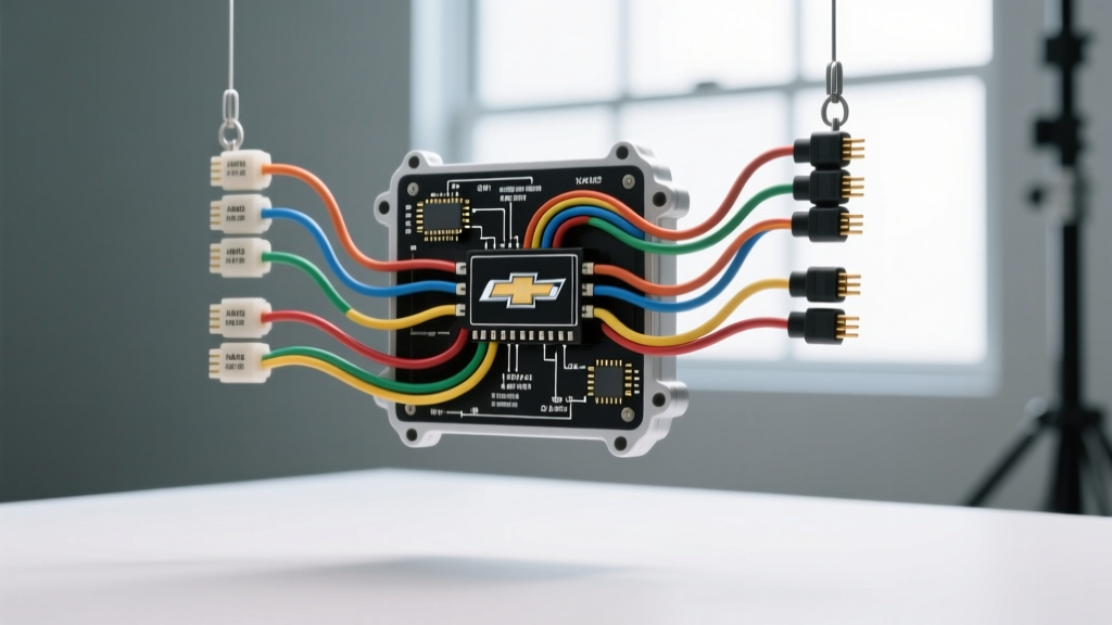
Navigating the Chevy 5.3 Vortec Engine Wiring Harness Diagram
When tackling an engine swap, PCM relocation, or diagnostic repair on GM's legendary LS-based 5.3L Vortec (Gen III LM7/L59 or Gen IV LC9/LMG), the factory wiring harness is the central nervous system. Relying on a comprehensive Chevy 5.3 Vortec engine wiring harness diagram is not just about finding which wire goes where; it is about understanding the financial and tooling commitments required to execute the job correctly. Whether you are swapping an LM7 into a classic muscle car or diagnosing a misfire on a 2004 Silverado, the costs and tools required scale dramatically based on your approach.
Harness Replacement and Repair Cost Breakdown
Before ordering parts, evaluate the condition of your current harness and the goals of your build. The financial difference between a dealer-direct replacement and a targeted DIY repair is substantial.
| Option | Estimated Cost | Pros | Cons |
|---|---|---|---|
| OEM GM Dealer Harness | $850 - $1,200 | Perfect fitment, OEM loom, updated part numbers | Prohibitive cost for budget swaps |
| Aftermarket Standalone (e.g., Painless) | $450 - $750 | Labeled wires, swap-friendly, removed emissions clutter | Requires custom routing, lacks OEM EMI shielding |
| Junkyard Pull (LM7/L59) | $150 - $300 | Cheap, retains factory emissions and EVAP | Brittle loom, corroded Metri-Pack seals, hidden chafing |
| DIY Pigtail & Terminal Repair Kit | $75 - $125 | Cost-effective, fixes specific faults permanently | Requires specialized crimping tools and pin extraction |
Essential Tooling for Vortec Harness Diagnostics and Pin-Terminal Work
You cannot properly service a 5.3L Vortec harness with standard electrical tape and generic crimpers. The Gen III and Gen IV PCM connectors utilize Delphi Metri-Pack 150 and 280 series terminals. Attempting to crimp these with standard closed-barrel pliers will result in high resistance, terminal push-out, and eventual PCM driver failure.
- Open Barrel Crimpers: You need a ratcheting open-barrel crimper calibrated for 18-22 AWG (Metri-Pack 150) and 12-16 AWG (Metri-Pack 280). The Delphi Connection Systems Catalog specifies exact crimp heights for these terminals to ensure gas-tight connections.
- Terminal Extraction Tools: The 80-pin C1 and C2 PCM connectors feature secondary locking mechanisms (TPAs). You require T-handled pin removal tools specifically shaped for Metri-Pack 150 cavities to release the locking tangs without snapping them.
- Low-Impedance Digital Multimeter: While a standard 10-Megohm DMM is fine for testing 12V power and grounds, diagnosing the 5.3L's PWM (Pulse Width Modulated) cooling fan circuits or DBW (Drive-By-Wire) pedal position sensors requires a True-RMS meter or an oscilloscope to read the rapid voltage switching.
- Adhesive-Lined Marine Heat Shrink: Never use electrical tape in the engine bay. The 5.3L Vortec generates immense heat, especially near the exhaust manifolds. Dual-wall, adhesive-lined polyolefin shrink (3M or equivalent) provides a waterproof seal and strain relief.
OEM Wire Gauge and Insulation Standards
When repairing or extending the 5.3L Vortec harness, matching the OEM wire gauge and insulation type is critical for both safety and signal integrity. The SAE J1128 standard dictates that engine compartment wiring must utilize Cross-Linked Polyethylene (XLPE) insulation, commonly referred to as GXL or TXL wire. Standard PVC wire (THHN) will melt when routed near the LS exhaust manifolds.
- 12 AWG (Red, Black, Pink): Used for main PCM battery feeds, main grounds, and high-current injector/coil power feeds. Requires Metri-Pack 280 terminals.
- 18 AWG (Various Colors): Used for injector control grounds, coil pack triggers, and idle air control (IAC) stepper motor circuits. Handles up to 16 amps in short bursts but relies on the PCM's internal current-limiting drivers.
- 20 AWG (Yellow, Tan, Dark Blue): Reserved for low-amperage sensor signals (MAF, CMP, CKP, ECT). Using thicker wire for these circuits can cause terminal push-out in the delicate Metri-Pack 150 cavities and alter the physical flexibility of the harness loom, leading to strain on the sensor connectors.
Gen III 5.3L (LM7) PCM Pinout & Diagram Reference
The following table outlines critical circuits from the Chevy 5.3 Vortec engine wiring harness diagram for the Gen III 80-pin PCM (Connectors C1 and C2). Note that wire colors may vary slightly by exact model year (1999-2006), but the pin assignments remain largely consistent for the LM7 and L59 platforms. Always verify against Helm Inc. GM Service Documentation for your specific VIN.
| Sensor / Actuator | PCM Connector & Pin | Wire Color | AWG | Function / Notes |
|---|---|---|---|---|
| MAF Signal | C2 - Pin 12 | Yellow | 20 | Analog frequency signal to PCM |
| MAF Ground | C2 - Pin 1 | Black/White | 20 | Dedicated sensor ground (do not splice to chassis) |
| CMP (Cam) Signal | C1 - Pin 53 | Brown | 20 | 1X cam signal for sequential fuel injection |
| CKP (Crank) Signal | C1 - Pin 54 | Dark Blue | 20 | 24X crank reluctor signal |
| Knock Sensor 1 | C1 - Pin 51 | Dark Blue | 20 | Front bank knock sensor (tuned to specific KHz) |
| Knock Sensor 2 | C1 - Pin 52 | Tan | 20 | Rear bank knock sensor |
| Injector 1 Control | C1 - Pin 1 | Dark Green | 18 | PCM switched ground (Pink wire is 12V feed) |
| Coil Pack 1 Control | C1 - Pin 3 | White | 18 | PCM trigger for COP ignition |
| PCM Battery (Hot) | C1 - Pin 20 | Red | 12 | Constant 12V for KAM (Keep Alive Memory) |
| PCM Main Ground | C1 - Pin 40 | Black | 12 | Must have less than 0.05V drop to engine block |
Common 5.3L Vortec Harness Failure Modes & Repair Costs
Understanding where the harness fails saves diagnostic time and prevents unnecessary PCM replacement. Based on field data and factory technical service bulletins, the 5.3L Vortec harness suffers from three primary failure modes:
1. Rear Cylinder Head Chafing (Cylinders 2, 4, 6, 8)
The factory harness routes tightly across the back of the passenger side cylinder head. Over time, engine torque and vibration cause the split loom to wear through, exposing the injector and coil pack wires to the sharp casting edges of the valve cover bolts. This results in intermittent misfires (P0300, P0302, etc.) that only appear under heavy load or high RPM. Repair Cost: $40 in materials (wire, shrink, loom) and 2 hours of labor to carefully depin the C1 connector, cut back to clean copper, and solder/crimp new pigtails.
2. MAP Sensor Oil Wicking
The MAP (Manifold Absolute Pressure) sensor pigtail is exposed to crankcase vapors. Over 150,000 miles, oil vapor condenses and wicks through the capillary action of the stranded copper wire, eventually pooling inside the PCM cavity and shorting the 5V reference circuit. Repair Cost: $25 for a new sealed MAP pigtail with a drip loop. If the PCM is damaged, replacement and reprogramming cost upwards of $350.
3. TCC Solenoid Wire Fatigue
The wires leading to the Torque Converter Clutch (TCC) PWM solenoid inside the transmission pan are subjected to extreme thermal cycling and fluid vibration. The insulation becomes brittle, leading to a short to ground and a P0740 or P1860 code. Repair Cost: $60 for a high-temp Teflon-jacketed pigtail and internal transmission filter kit.
Final Diagnostic and Cost-Saving Workflow
Before purchasing a replacement harness, always perform a voltage drop test on the PCM power and ground circuits using your DMM. A voltage drop greater than 0.10V on the 12 AWG ground wires indicates corrosion at the engine block splice pack, which can mimic a failing PCM or bad sensor. By leveraging the Chevy 5.3 Vortec engine wiring harness diagram alongside proper Metri-Pack tooling, you can execute permanent, OEM-quality repairs for a fraction of the dealer replacement cost.