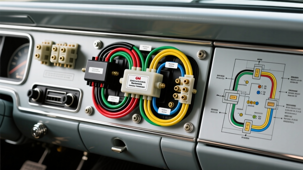
Understanding the 67-72 C10 Ignition Switch Architecture
The 1967 through 1972 Chevrolet C10 (along with the C20, C30, and K-series variants) represents a golden era of GM truck engineering. When diagnosing electrical gremlins or performing a custom harness swap, understanding the 67-72 C10 ignition switch wiring diagram is mandatory. Unlike modern vehicles that rely on Body Control Modules (BCMs) and CAN-bus networks, these classic trucks utilize a direct, hard-wired analog circuit. Power flows mechanically through a dash-mounted or column-proximate 4-terminal rotary switch, distributing 12-volt DC power to the fuse block, ignition coil, and starter solenoid.
While the physical bezel and mounting locations shifted slightly between the 1967-1969 'Action Line' dash and the 1970-1972 updated interior, the core electrical logic of the GM 4-post ignition switch remained remarkably consistent. This complete walkthrough will trace the current flow from the battery to the starter, decode OEM wire colors, detail AWG specifications, and provide expert-level troubleshooting for common voltage drop failures.
The Core 4-Terminal GM Ignition Switch Pinout
The back of the classic GM ignition switch features a 4-terminal plug. Identifying these posts and their corresponding OEM wire colors is the first step in reading any 67-72 C10 ignition switch wiring diagram. Below is the definitive pinout specification chart based on factory GM assembly manuals.
| Terminal ID | OEM Wire Color | AWG Size | Circuit Function | Hot In Key Position |
|---|---|---|---|---|
| BAT (Battery) | Red | 10 AWG (or 8 AWG) | Main constant 12V power feed from the horn relay bus bar or starter solenoid. | OFF, ACC, RUN, START |
| IGN (Ignition) | Pink | 12 AWG | Feeds the ignition coil, HEI module, and the 'IGN' bus on the fuse block. | RUN, START |
| ACC (Accessory) | Brown (or Orange) | 12 AWG | Feeds the 'ACC' bus on the fuse block (wipers, radio, heater blower). | ACC, RUN |
| ST / SOL (Start) | Yellow (67-68) / Purple (69-72) | 12 AWG | Engages the starter solenoid 'S' terminal via the neutral/clutch safety switch. | START (Spring Return) |
Note: The transition from Yellow to Purple for the starter solenoid feed wire occurred around 1969 as GM standardized its chassis wiring color codes across passenger cars and light trucks.
Complete Circuit Walkthrough: Tracing the Power
To truly master the 67-72 C10 ignition switch wiring diagram, you must trace the circuit dynamically. Let us follow the electrons from the battery through the switch and out to the vital truck systems.
Step 1: Battery to the Horn Relay Bus Bar
Power originates at the battery positive terminal and travels via a heavy-gauge cable (typically 4 AWG or 2 AWG) to the starter motor. At the starter solenoid's main battery post, a smaller pigtail branches off. In many 67-72 C10 configurations, this pigtail routes to the horn relay, which acts as a central forward junction block (bus bar) located on the driver-side inner fender. From this bus bar, the main harness feed begins its journey through the firewall bulkhead connector toward the ignition switch.
Step 2: The Fusible Link and Main BAT Feed
Before reaching the firewall, the main 10 AWG Red wire is protected by a 14 AWG fusible link. According to classic GM engineering standards (and referenced in SAE J1128 Low Tension Primary Cable specifications), a fusible link must be exactly four wire gauges smaller than the circuit it protects. This 14 AWG link features thick, spongy Hypalon insulation designed to contain heat and prevent under-hood fires in the event of a dead short. The Red 10 AWG wire then passes through the engine-side bulkhead connector, through the dash, and terminates at the BAT terminal on the ignition switch.
Step 3: Ignition (IGN) and the Resistance Wire Nuance
When the key is turned to RUN or START, the internal copper wiper bridges the BAT and IGN terminals. Power exits the switch on a 12 AWG Pink wire. This pink wire routes to the fuse block to energize the turn signals, gauges, and ignition system. Critical Expert Note: If your 67-72 C10 retains its original points-style distributor, the branch of the pink wire leading to the coil positive (+) is actually a specialized GM resistance wire. This wire drops the 12V system voltage down to approximately 9V to prevent the breaker points from arcing and burning. If you are upgrading to an HEI (High Energy Ignition) distributor, you must bypass or replace this resistance wire with a standard 12 AWG copper wire to ensure the HEI module receives a full 12 volts; otherwise, the truck will suffer from weak spark and misfires under load.
Step 4: Accessory (ACC) and the Fuse Block
In the ACC and RUN positions, the switch bridges power to the Brown (or Orange) 12 AWG wire. This circuit feeds the accessory side of the glass-tube fuse block. Components like the windshield wiper motor, cabin heater blower, and optional AM/FM radio draw from this circuit. Because these loads can be substantial (especially aging wiper motors drawing 10+ amps), the ACC terminal inside the switch is highly prone to thermal fatigue and internal pitting over decades of use.
Step 5: Start (ST) and the Solenoid Engagement
When the key is twisted to the START position, a heavy internal spring-loaded contact bridges the BAT terminal to the ST terminal. Power exits on the 12 AWG Purple (or early Yellow) wire. This wire does not go straight to the starter; it first routes to the firewall and connects to a safety interlock. On automatic transmission C10s, this wire passes through the column-mounted or transmission-mounted Neutral Safety Switch. On 4-speed manual trucks, it routes through a clutch pedal depression switch. Once the safety condition is met, the Purple wire carries 12V directly to the 'S' terminal on the starter solenoid, pulling the plunger, engaging the Bendix drive, and closing the main high-amperage contacts to spin the starter motor.
Real-World Troubleshooting: Voltage Drop and Pitting
The most common failure mode in the 67-72 C10 ignition circuit is not a broken wire, but internal switch degradation and bulkhead connector corrosion. Use a digital multimeter (DMM) set to DC Volts to perform these diagnostic tests:
- Symptom: Truck starts but immediately dies when the key is released from START to RUN.
Diagnosis: The IGN (Pink) terminal inside the switch is pitted, or the fuse block IGN bus tab is corroded. Perform a voltage drop test by placing the red DMM probe on the BAT terminal and the black probe on the Pink IGN wire with the key in RUN. A drop greater than 0.2V indicates a failing switch. - Symptom: No crank, but headlights and dash accessories work perfectly.
Diagnosis: Trace the Purple ST wire. Check for voltage at the ignition switch side of the neutral safety switch while a helper holds the key in START. If you have 12V entering the switch but 0V exiting, the neutral safety switch is misaligned or internally corroded. - Symptom: Intermittent loss of gauges or wipers.
Diagnosis: Inspect the engine-side bulkhead connector. Decades of engine bay heat and moisture cause the female pins on the ACC (Brown) and IGN (Pink) circuits to oxidize, creating a high-resistance bottleneck. Clean with electrical contact cleaner and apply dielectric grease.
Modernizing the Classic C10 Ignition Harness
While the factory 67-72 C10 ignition switch wiring diagram is a masterpiece of analog simplicity, pushing 50-year-old copper through a tiny rotary switch to power modern accessories is a recipe for melted plastics and voltage drops. Professional restomod builders utilize the 'Ignition Relay Upgrade'.
By installing a standard Bosch-style 30A/40A SPDT relay, you remove the heavy amperage load from the dash switch. Wire the relay's trigger coil (Terminals 85 and 86) to the original 12 AWG Pink IGN wire. Connect the relay's high-current switch terminals (Terminal 30 to a fused 10 AWG direct battery feed, and Terminal 87 to the fuse block's IGN bus). Now, the dash ignition switch only carries the milliamp load required to trigger the relay coil, while the heavy current flows directly from the battery to the fuse block. This ensures your HEI ignition, modern gauges, and electric fuel pumps receive a rock-solid 14.2 volts while the alternator is charging, vastly extending the life of your OEM ignition switch.
Authoritative References and Further Reading
For factory-accurate schematics and engineering standards, consult the following resources:
- GM Heritage Center Vehicle Information Kits - Provides original 1967-1972 Chevrolet Truck Assembly Manuals and chassis wiring schematics.
- SAE International J1128 Standard - The definitive specification for Low Tension Primary Cable used in automotive wiring harnesses, including fusible link gauge requirements.
- Classic Industries Chevrolet Truck Catalogs - Excellent visual references for bulkhead connector pinouts and OEM wire color routing.