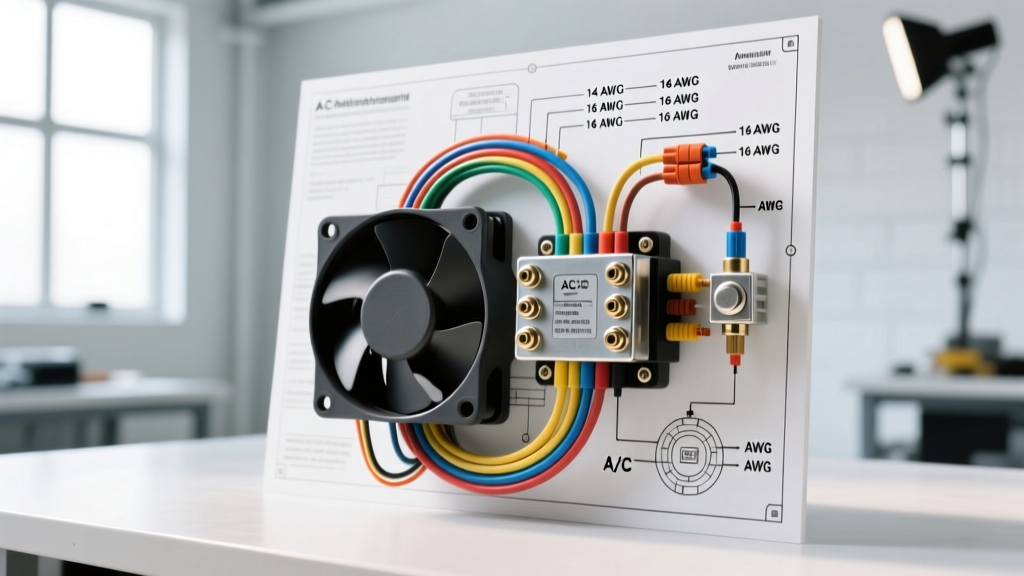
Introduction to Dual Fan Cooling and A/C Integration
Upgrading to an electric dual fan setup is one of the most effective modifications you can make to improve engine cooling and free up parasitic horsepower. However, a frequent stumbling block for beginners is properly integrating the cooling fans with the vehicle's air conditioning system. If you are searching for a reliable dual fan relay wiring diagram with AC integration, you are in the right place. When the A/C compressor engages, the refrigerant circulating through the condenser (mounted directly in front of your radiator) absorbs massive amounts of heat. Without adequate airflow from a dedicated condenser fan, A/C head pressures will spike, causing the high-pressure cut-off switch to trip and resulting in warm cabin air or damaged compressor seals.
This beginner-friendly guide breaks down the exact wiring logic, wire gauge requirements, and relay pinouts needed to wire two electric fans so that Fan 1 operates based on engine coolant temperature, while Fan 2 kicks on automatically the moment the A/C compressor clutch is engaged.
Essential Components and Wire Sizing Specifications
Before cutting a single wire, you must gather the correct automotive-grade components. Never use household wire or solid-core copper for automotive applications; vibrations will cause solid core to snap, and non-rated insulation will melt. Always adhere to SAE J1128 Primary Cable Standards for stranded, cross-linked polyethylene (XLPE) or PVC automotive wire.
| Circuit Application | Recommended AWG | Max Amperage | Standard SAE Color Code | Connector Type |
|---|---|---|---|---|
| Battery to Fuse Block | 8 AWG | 40A - 50A | Red | 5/16' Ring Terminal (Heat Shrink) |
| Fuse to Relay (Pin 30) | 10 AWG | 30A | Red | Metri-Pack 280 Female |
| Relay to Fan Motor (Pin 87) | 10 AWG | 30A | Blue (Fan 1) / Yellow (Fan 2) | Metri-Pack 280 Female or Spade |
| Relay Trigger (Pin 85) - ECU | 18 AWG | 3A | Light Green | Deutsch DT or Solder-Seal Splice |
| Relay Trigger (Pin 85) - A/C Clutch | 16 AWG | 5A | Dark Green | T-Tap (Discouraged) or Solder-Seal |
| Relay & Fan Grounds (Pin 86) | 10 AWG / 18 AWG | 30A / 3A | Black | Ring Terminal to Chassis |
Understanding the Standard Bosch-Style 4-Pin Relay
The foundation of any robust dual fan relay wiring diagram with AC logic is the standard ISO/Bosch-style 4-pin relay. According to the Hella Automotive Relay Technical Guide, these relays use a standardized numbering system across the automotive industry:
- Pin 30 (Power In): Receives constant 12V+ from the battery via a fuse.
- Pin 87 (Power Out): Sends 12V+ to the fan motor's positive terminal when the relay is triggered.
- Pin 86 (Coil Ground): Provides the ground path for the internal electromagnetic coil.
- Pin 85 (Coil Trigger): Receives a 12V+ signal from a switch, ECU, or A/C clutch wire to activate the coil.
Expert Note: While pins 85 and 86 are electrically interchangeable on a basic relay, if your relay contains an internal suppression diode (used to protect sensitive ECUs from voltage spikes), Pin 85 MUST be the trigger (+) and Pin 86 MUST be the ground (-). Always check the schematic printed on the relay casing.
Circuit 1: Primary Cooling Fan (Engine Temperature)
The primary fan (Fan 1) is responsible for maintaining baseline engine temperatures. It is triggered by the vehicle's Engine Control Unit (ECU) or an aftermarket adjustable thermostat switch.
- Power Feed: Run 8 AWG wire from the battery positive terminal to an inline 30A ATO fuse holder, then transition to 10 AWG wire into the relay harness at Pin 30.
- Ground Path: Connect Pin 86 to a clean, bare-metal chassis ground using a 10 AWG black wire and a crimped ring terminal. Apply dielectric grease to prevent corrosion.
- Output: Connect Pin 87 to the positive terminal of Fan 1 using 10 AWG wire.
- Trigger Signal: Connect Pin 85 to the ECU's dedicated cooling fan trigger output using 18 AWG wire. When the coolant reaches the ECU's programmed threshold (usually 210°F - 225°F), the ECU provides a 12V+ signal (or completes a ground path, depending on the manufacturer) to close the relay circuit.
Circuit 2: Secondary Condenser Fan (A/C Integration)
This is where the dual fan relay wiring diagram with AC integration comes into play. Fan 2 must pull air across the A/C condenser whenever the compressor clutch is engaged, regardless of engine temperature.
- Power Feed: Identical to Circuit 1. Battery -> 30A Fuse -> Relay Pin 30.
- Ground Path: Relay Pin 86 to chassis ground.
- Output: Relay Pin 87 to the positive terminal of Fan 2.
- The A/C Trigger Tap: Locate the wire that supplies 12V+ to the A/C compressor clutch coil (usually found near the compressor or the A/C accumulator). Using an 18 AWG dark green wire, tap into this 12V+ clutch signal. Route this wire to Pin 85 of Relay 2.
How it works: When you turn on the cabin A/C, the climate control module energizes the compressor clutch. That exact same 12V+ signal travels down your tapped wire to Pin 85 of Relay 2, instantly triggering the condenser fan. When the A/C cycles off, the fan shuts off, reducing electrical load on the alternator.
Critical Protection: Flyback Diodes and ECU Safety
A common beginner mistake that leads to fried ECUs or blown A/C control switches is ignoring inductive kickback. When the electromagnetic coil inside a relay is de-energized, the collapsing magnetic field generates a reverse voltage spike (often exceeding 100V for a fraction of a millisecond). If your ECU or A/C switch is providing the trigger signal to Pin 85, this spike travels backward into the sensitive solid-state driver, destroying it.
The Fix: Always use relays with an internal flyback diode or resistor when triggering from an ECU. If using a standard relay, solder a 1N4001 diode across the relay socket terminals for Pins 85 and 86, with the diode's cathode (the stripe) pointing toward the 12V+ trigger source (Pin 85). This creates a safe loop for the voltage spike to dissipate.
Troubleshooting Common Wiring Mistakes
Even with a perfect diagram, physical wiring errors occur. Use a digital multimeter (DMM) to verify your setup. For deeper diagnostic procedures, reference the Haynes Relay Testing & Replacement guide. Here are the most frequent failure modes:
1. Fan Runs Hot and Slow (Voltage Drop)
Symptom: The fan spins, but lacks the torque to pull air at idle, and the relay wiring feels hot to the touch.
Cause: Using wire that is too thin (e.g., 14 AWG for a 25A fan motor) or relying on a rusty chassis ground.
Fix: Perform a voltage drop test. Place your DMM probes on the battery positive and the fan's positive terminal while the fan is running. A reading higher than 0.2V indicates excessive resistance. Upgrade to 10 AWG and scrape the paint off your ground locations down to bare, shiny steel.
2. A/C Fan Triggers, But Compressor Doesn't Engage
Symptom: Fan 2 turns on when the A/C button is pressed, but the cabin blows warm air and the clutch doesn't click.
Cause: Tapping the trigger wire on the 'load' side of a failing A/C clutch coil, or the tap is drawing too much current and dropping the voltage below the clutch's engagement threshold.
Fix: Ensure your tap is clean. If the relay coil is drawing too much current, install a secondary 'isolator' relay so the A/C clutch wire only triggers a low-amp relay, which then triggers the high-amp fan relay.
3. Fans Do Not Shut Off When Key is Removed
Symptom: The dual fans continue to run after the ignition is turned off, eventually draining the battery.
Cause: Wiring the relay trigger (Pin 85) to a constant 12V source instead of a switched ignition source, or a stuck ECU driver.
Fix: Verify that the ECU or thermostat switch only receives power when the ignition is in the 'ON' or 'RUN' position. If using a standalone toggle switch for testing, ensure it is routed through an ignition-switched fuse block terminal.
Final Assembly and Weatherproofing
Underhood environments are brutal. Heat, water, oil, and vibration will destroy cheap connections. Avoid 'Scotchlok' T-taps for your A/C clutch trigger wire; they pierce the insulation, inviting copper oxidation and green corrosion. Instead, strip a small section of the clutch wire, wrap your 18 AWG trigger wire around it, solder the joint, and seal it with an adhesive-lined marine-grade heat shrink tube. Mount your relays in a sealed, fused relay block (such as a Painless Performance or Bussmann RTMR block) away from exhaust headers and moving radiator linkages. By following this dual fan relay wiring diagram with AC logic, you ensure your engine stays cool in traffic and your A/C blows ice-cold at idle.