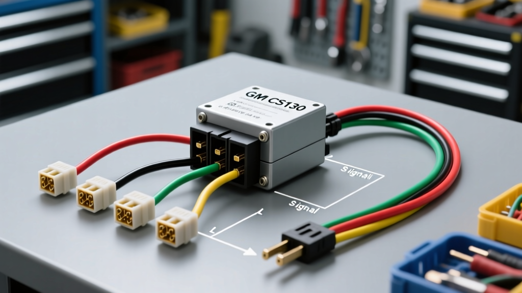
Architecture of the Delco CS130 Internal Regulator
Introduced in 1987, the Delco CS130 (Charging System 130mm) alternator and its integrated internal voltage regulator represented a massive leap in General Motors' electrical architecture. Replacing the older SI10 series, the CS130 was designed to produce higher amperage at idle RPMs to support the growing electrical loads of early OBD1 engine control modules, electric cooling fans, and fuel injection systems. While the regulator is physically mounted inside the alternator housing, it is serviced as an independent module. Understanding the wiring diagram voltage regulator pinout for the CS130 is critical, as improper wiring of the 4-pin connector is the leading cause of premature diode trio failure, overcharging, and parasitic battery drain.
This technical specification reference details the exact pin configurations, OEM wire color codes, AWG routing requirements, and real-world diagnostic decision trees for the GM CS130 and its high-output sibling, the CS144.
CS130 4-Pin Voltage Regulator Wiring Diagram Breakdown
The CS130 utilizes a rectangular 4-pin connector, though early or base-model vehicles may only have two or three wires populated in the harness. The pins are labeled P, I, L, and S. Each serves a distinct electrical function that dictates the regulator's pulse-width modulation (PWM) of the rotor field coil.
Terminal S (Sense) Circuit Specifications
The Sense terminal is the most critical pin on the regulator. It measures the actual voltage at the vehicle's primary electrical distribution point or battery positive terminal. The regulator uses this data to adjust the field current to the rotor.
- Wire Gauge: 14 AWG or 12 AWG stranded copper.
- Routing Rule: Must be routed directly to the battery positive post or the main under-hood fuse block distribution bus.
- Fusing: Requires an inline 10A AGC or MAXI fuse within 18 inches of the battery connection point to protect against harness shorts.
- Critical Failure Mode: If the S terminal is jumpered directly to the alternator's BATT output stud (a common "shortcut" in amateur wiring), the regulator will sense voltage after the voltage drop of the main output cable. Under high electrical load, the cable experiences voltage drop, the S terminal reads low voltage, and the regulator overcompensates by pushing 15.5V+ into the system, boiling the battery and frying sensitive ECU logic boards.
Terminal L (Lamp) Circuit & Excitation Logic
The Lamp terminal serves a dual purpose: it grounds the dashboard charge indicator lamp and provides the initial excitation current (typically 35mA to 50mA) to "wake up" the alternator's rotor field when the engine starts.
- Wire Gauge: 18 AWG to 20 AWG.
- Resistance Requirement: The circuit requires a minimum resistance to prevent backfeeding. In OEM applications, a standard 194 incandescent dash bulb provides the necessary resistance.
- LED Dash Modification: If the vehicle's dashboard has been upgraded to LEDs, the lack of filament resistance will cause the regulator to fail to excite, or worse, allow AC ripple to backfeed through the diode trio, destroying the regulator. You must solder a 50-ohm to 100-ohm, 2-watt resistor in parallel with the LED bulb or inline on the L wire to simulate incandescent resistance.
Terminal I (Ignition) & Terminal P (Phase)
Terminal I (Ignition): Receives 12V+ from a key-on/switched ignition source. This tells the regulator that the engine is running and prepares the internal logic gates for charging. It is typically wired via an 18 AWG Pink or Pink/Black wire sourced from the ignition switch's "Run" terminal.
Terminal P (Phase): Taps into one of the stator windings to provide a tachometer signal or PCM input. It outputs a square-wave pulse at exactly half of the engine's crankshaft RPM. In many standard applications, this pin is left unpopulated unless the vehicle's ECM requires a dedicated tach signal for fuel injector timing reference.
OEM Wire Color Codes & AWG Specification Chart
The following table outlines the standard GM OEM specifications for the CS130 harness. Always verify with a multimeter, as previous owners or aftermarket harness manufacturers may deviate from factory color codes.
| Terminal | Function | OEM Wire Color | AWG Size | Voltage / Resistance Spec |
|---|---|---|---|---|
| BATT | Main Alternator Output | Red (Heavy Cable) | 8 AWG to 4 AWG | 13.8V - 14.4V (Target) |
| S | Battery Voltage Sense | Red | 14 AWG - 12 AWG | Battery V + 0.2V Max Drop |
| L | Lamp / Excitation | Brown | 18 AWG - 20 AWG | 12V (Key On, Engine Off) |
| I | Ignition Wake-Up | Pink / Pink-Black | 18 AWG | 12V+ (Switched Ignition) |
| P | Phase / Tach Signal | White / Gray | 20 AWG | AC Pulse (Half Engine RPM) |
Real-World Failure Modes & Diagnostic Decision Tree
When diagnosing CS130 charging system faults, avoid the trap of immediately replacing the alternator. Use this decision tree to isolate harness and regulator faults based on empirical multimeter data.
Symptom 1: Alternator Whines and Overcharges (15.0V+)
- Test: Measure voltage at the battery positive post, then measure voltage at the alternator BATT stud while the engine is idling with headlights and HVAC blower on high.
- Analysis: If the BATT stud reads 14.8V but the battery post reads 13.2V, you have a massive voltage drop (1.6V) on the main output cable due to corrosion or undersized wire.
- Verify S-Circuit: Probe the S terminal wire at the regulator connector. If the S wire is reading 14.8V (matching the BATT stud), it is incorrectly wired to the alternator output instead of the battery. The regulator is accurately compensating for a voltage drop it shouldn't be seeing.
- Resolution: Reroute the S terminal wire directly to the battery positive terminal or main distribution block. Upgrade the main BATT output cable to 4 AWG welding cable if running a 100A+ load.
Symptom 2: No-Charge Condition Until Engine is Revved to 2500+ RPM
- Test: Check for 12V at the L terminal wire (harness side) with the key in the "ON" position and the engine off.
- Analysis: If 12V is missing, the excitation circuit is open. The alternator relies on residual magnetism to self-excite at high RPMs, but requires the L terminal current to initiate charging at idle.
- Verify Dash Bulb: Check if the dashboard "GEN" or "ALT" bulb is burned out. A burned-out incandescent bulb breaks the circuit.
- Resolution: Replace the dash bulb. If an LED conversion was performed, install a 50-ohm, 2-watt bypass resistor inline on the Brown L wire to restore the excitation current path.
Symptom 3: ECU Resets, Radio Static, and Flickering Dash Lights
- Test: Set your digital multimeter to AC Volts (VAC). Connect the probes to the battery positive and negative terminals while the engine is running.
- Analysis: A healthy CS130 should produce less than 50mV (0.050V) of AC ripple. If you read >150mV AC, the internal diode trio or the rectifier bridge has failed, allowing AC stator current to bleed into the DC vehicle harness.
- Resolution: The voltage regulator and rectifier assembly must be replaced. Note: High AC ripple is frequently caused by a failing battery with an open internal cell, which forces the alternator to operate at 100% duty cycle, overheating the regulator. Always load-test the battery when replacing a CS130 regulator.
Upgrading to CS144 and 1-Wire Alternator Conversions
For high-amperage applications (winches, massive car audio systems, or heavy off-road lighting), the CS130's 100A-105A limit is often insufficient. The CS144 utilizes the exact same 4-pin regulator wiring diagram and connector, but features a larger 144mm stator housing capable of 140A+ output. When upgrading to a CS144, the main BATT output cable must be upgraded to a minimum of 2 AWG or 1/0 AWG pure copper cable, and the main chassis ground must be equivalently upgraded to prevent ground-loop voltage drops.
Alternatively, many restomod builders opt for a "1-Wire" CS130 conversion. A 1-wire regulator internally jumperes the S and I terminals directly to the BATT output stud. While this simplifies the wiring diagram voltage regulator harness to a single heavy gauge cable, it sacrifices low-RPM charging performance. A 1-wire alternator will not begin charging until the engine is revved past 1,500 RPM to generate sufficient residual magnetic field collapse, making it unsuitable for vehicles that spend extensive time idling in traffic.
Authoritative References & Engineering Standards
- SAE J1171: Electrical Connections for Automotive Applications - Standards for terminal retention and voltage drop limits in high-vibration environments.
- Mad Electrical CS130 Technical Guide - Comprehensive bench-testing procedures and diode trio resistance specifications for Delco CS series alternators.
- Remy Power Generation (Delco Remy) Service Manuals - OEM torque specifications (50-65 in-lbs for BATT terminal nut) and PWM regulator logic flowcharts.