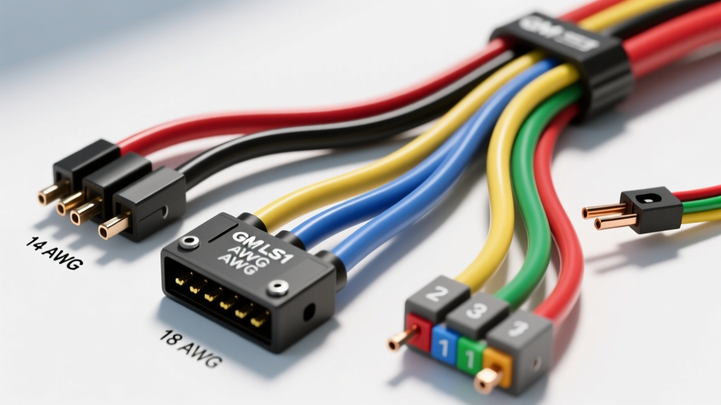
Introduction to Car Electrical Schematics
When beginners first open a factory service manual, the sheer volume of lines, nodes, and symbols found in car electrical schematics can feel like reading an alien language. Unlike a physical wiring diagram that attempts to show where a wire is routed through the chassis, an electrical schematic is a logical map. It illustrates how current flows from the power source, through switches, relays, and sensors, and finally to ground. Understanding this distinction is the first and most critical step in automotive electrical diagnostics.
For this beginner-friendly fundamentals guide, we will decode these concepts using one of the most popular and widely swapped engine platforms in the world: the General Motors LS1 V8 (specifically the 1997-2002 F-Body/Camaro application). By applying universal schematic principles to a real-world harness, you will learn how to trace circuits, identify wire gauges, and properly read ECU pinouts.
The Anatomy of a Wiring Schematic: Symbols and Rules
Before diving into the GM LS1 Powertrain Control Module (PCM) harness, you must understand the foundational rules of reading schematics. According to the SAE J1128 Low Tension Primary Cable Standard, wire identification and circuit logic follow strict conventions.
The "Mating Face" Rule
The most common mistake beginners make is misidentifying connector pins. In car electrical schematics, connector cavity maps are always drawn from the mating face (terminal side), not the wire side. If you are looking at the back of a connector where the wires enter, the pin layout will be mirrored. Always flip your perspective to match the schematic when back-probing a connector.
Splices and Ground Nodes
- Solid Dots (Nodes): A solid black dot where two or more wires intersect indicates a physical splice (often a soldered joint or ultrasonic weld inside the harness loom).
- Crossing Lines (No Dot): If two wires cross on a schematic without a solid dot, they do not connect. They merely cross paths in the drawing for space efficiency.
- Ground Symbols: A standard chassis ground is represented by three descending horizontal lines. A "signal ground" or "sensor ground" (which returns directly to the PCM without touching the chassis) is often depicted as a hollow triangle or a ground symbol with a line through it.
Practical Case Study: The GM LS1 PCM Harness
The 1997-2002 GM LS1 engine utilizes a complex, multi-connector PCM harness. The PCM features three primary 80-way Delphi connectors, color-coded for logical separation. Understanding this color-coding is a massive shortcut when reading LS1 car electrical schematics.
Connector Breakdown
| Connector Color | Designation | Primary Function | Common Wire Gauge (AWG) |
|---|---|---|---|
| Blue | C1 | Sensors, Fuel Injectors, MAF, TPS | 18 AWG to 20 AWG |
| Red | C2 | Ignition Coils, Serial Data, PCM Grounds | 16 AWG to 20 AWG |
| Black | C3 | Main Power Feeds, EVAP, Actuators, Relays | 12 AWG to 18 AWG |
Decoding Wire Colors and AWG Specifications
Car electrical schematics rely heavily on wire color codes and American Wire Gauge (AWG) sizes to convey circuit purpose and current capacity. In GM schematics, a wire listed as PPL/WHT means the base color is Purple, with a White tracer stripe. If no tracer is listed, it is a solid color.
Current Draw and AWG Selection
Wire gauge is determined by the amperage the circuit must carry and the distance the wire must travel to prevent excessive voltage drop. Referencing the Helm Incorporated GM Service Manuals, we can see specific AWG applications in the LS1 harness:
- Main PCM Battery Feed (Circuit 1020): Uses 12 AWG Red wire. This circuit supplies constant battery voltage to the PCM's Keep Alive Memory (KAM). The thicker gauge prevents voltage drop that could cause PCM resets or memory loss.
- Fuel Injector Power (Circuit 439): Uses 18 AWG Pink wire. LS1 injectors are high-impedance (approx. 12 ohms). They draw roughly 1 amp each during the initial peak-and-hold saturation phase. 18 AWG is sufficient to handle the localized current without excessive heat buildup in the engine bay.
- MAF Sensor Signal (Circuit 492): Uses 20 AWG Yellow wire. The Mass Air Flow sensor outputs a low-amperage frequency or voltage signal back to the PCM. Because current draw is negligible (milliamps), a thin 20 AWG wire is used to save weight and harness bulk.
LS1 PCM C1 (Blue) Sensor Pinout Reference
Below is a structured reference table for critical engine sensors terminating at the C1 Blue Connector. This table mimics the data you will extract from factory car electrical schematics when diagnosing a driveability issue.
| Component | Pin Number | Circuit Number | Wire Color | AWG | Signal Type |
|---|---|---|---|---|---|
| MAF Sensor Signal | 36 | 492 | Yellow | 20 | Frequency (Hz) |
| TPS Signal | 48 | 416 | Dark Blue | 20 | Analog Voltage (0-5V) |
| IAT Sensor Signal | 16 | 472 | Black | 20 | Thermistor (Variable Resistance) |
| CTS Sensor Signal | 68 | 410 | Yellow/Black | 20 | Thermistor (Variable Resistance) |
| Injector 1 Control | 83 | 468 | Brown | 18 | Switched Ground (PWM) |
Real-World Troubleshooting: Applying the Schematic
Let us apply these schematic fundamentals to a common LS1 failure mode: Engine cranks, but will not start (No Injector Pulse).
Step 1: Verify Power Feeds (The Logical Flow)
Do not immediately start probing the injectors. Look at the schematic for the injector power feed. The LS1 injectors receive constant 12V from the fuel pump relay/fuse block via the Pink (18 AWG) wires. Using a high-impedance Digital Multimeter (DMM), back-probe the Pink wire at any injector connector with the key in the "ON" position. If you read 0V, the fault is upstream (likely the IGN 1 fuse or a failed main relay), not the PCM.
Step 2: Check the PCM Grounds
If power is present, the PCM needs a solid ground path to fire the injector solenoids. Check the C2 (Red) connector. Pins 1, 2, 3, 4, 5, and 6 are dedicated PCM grounds (Black/White wires, 16 AWG). Perform a voltage drop test across these ground pins to the engine block. A reading above 0.10V under cranking load indicates a corroded grounding node (often G102 or G104 on the passenger cylinder head), which will prevent the PCM's internal low-side drivers from pulling the injector circuit to ground.
Step 3: Inspect the Crankshaft Position Sensor (CKP)
The PCM will not fire the injectors without a synchronization signal from the CKP sensor. According to the Haynes GM LS-Series Engine Rebuild Manual, the CKP sensor on early LS1s is a magneto-resistive 2-wire sensor located at the 4 o'clock position on the block. Check the schematic for the CKP High (Circuit 613, Dark Blue) and CKP Low (Circuit 612, Purple) wires. Because this is a low-level AC signal, you must use an oscilloscope or a DMM set to AC Millivolts while cranking to verify the signal is reaching the C1 Blue connector (Pins 21 and 22).
Essential Tools for Schematic Tracing
To properly interact with the circuits defined in car electrical schematics without causing secondary damage, you must use the correct tools:
- T-Pin Back-Probes: Never pierce wire insulation with a needle or safety pin. Piercing breaches the copper stranding, allowing moisture ingress and eventual green rot (copper oxidation), which increases resistance and causes phantom electrical gremlins. Always use specialized T-pins to slide past the connector's silicone weather seals.
- High-Impedance DMM: Never use an incandescent test light on modern PCM circuits. A test light draws significant current (often 2-4 amps) to illuminate the bulb, which can instantly fry the PCM's fragile low-side driver transistors. Always use a DMM with a minimum 10-megohm impedance.
- Power Probe: For testing power feeds and grounds (but never PCM signal wires), a Power Probe allows you to apply 12V or ground directly to a circuit while monitoring amperage draw, saving hours of diagnostic time.
Summary
Mastering car electrical schematics requires shifting your mindset from physical routing to logical flow. By understanding the mating face rule, respecting AWG current limits, and systematically tracing power and ground nodes using a high-impedance DMM, you can diagnose complex automotive electrical faults with confidence. Keep your factory service manuals close, respect the Delphi connector weather seals, and always let the schematic dictate your diagnostic path.