Introduction to RV and Camper Van Power Protection
When converting a Sprinter, Transit, or Express van into a camper, or when maintaining a Class A/B/C motorhome, protecting your sensitive automotive and residential electronics is non-negotiable. Shore power pedestals at RV parks are notorious for voltage spikes, reversed polarity, and open neutrals. A hardwired Electrical Management System (EMS) acts as a comprehensive shield. Understanding the wiring diagram for surge protector units is the first step toward a safe, code-compliant installation. Unlike portable units that plug directly into a 30-amp TT-30R receptacle, hardwired units require precise integration into your vehicle's main AC distribution panel. This guide breaks down the exact wiring schematics, performs a comprehensive cost analysis, and details the specialized tool requirements needed to execute a flawless installation.
Decoding the Wiring Diagram for Surge Protector Systems
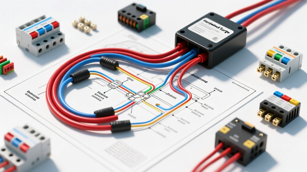
The standard wiring diagram for a 30-amp hardwired EMS (such as the industry-standard Progressive Industries EMS-HW30C) revolves around a 'Line' and 'Load' configuration. The diagram dictates that shore power enters the 'Line' side of the EMS, passes through the internal contactor and monitoring board, and exits the 'Load' side to feed your RV's main AC breaker panel.
For automotive camper conversions, space is at a premium. The EMS unit is typically mounted in the rear garage or under a bench seat, requiring careful routing of 10 AWG THHN stranded wire through flexible liquid-tight conduit to protect against chassis vibration and abrasion. The diagram also includes a low-voltage segment for the remote digital display. While the main power is 120V AC, the display monitor often requires a 12V DC tap from your vehicle's auxiliary battery bank or house battery fuse block to remain illuminated when the RV is running off the chassis alternator or inverter.
30-Amp Shore Power Pinout and Color Codes
Adhering to NFPA 70 (National Electrical Code) Article 551 for recreational vehicles, your wire color codes must strictly match standard AC conventions. Miswiring the neutral and ground can cause the EMS to instantly fault and lock out power.
| Terminal Designation | Wire Color (AC) | AWG Size | Function |
|---|---|---|---|
| LINE (Hot) | Black | 10 AWG THHN | Receives 120V from shore power cord |
| LINE (Neutral) | White | 10 AWG THHN | Return path for shore power |
| LINE (Ground) | Green / Bare | 10 AWG THHN | Chassis and pedestal earth ground |
| LOAD (Hot) | Black | 10 AWG THHN | Feeds main AC distribution panel |
| LOAD (Neutral) | White | 10 AWG THHN | Feeds main AC neutral bus bar |
| LOAD (Ground) | Green / Bare | 10 AWG THHN | Feeds main AC ground bus bar |
| Display (12V+) | Red | 18 AWG | 12V DC from house battery fuse block |
| Display (12V-) | Black | 18 AWG | 12V DC common ground |
Cost Analysis: Hardwired EMS vs. Portable Alternatives
From a budget perspective, building out a camper van's electrical system requires balancing upfront component costs against long-term reliability. A portable 30-amp surge protector is cheaper initially and requires zero installation labor, but it is vulnerable to theft and occupies valuable exterior storage space. A hardwired EMS requires a higher initial investment in materials and tools but offers superior protection, permanent integration, and internal bypass capabilities.
Itemized Installation Cost Breakdown
| Component / Material | Estimated Cost (USD) | Notes |
|---|---|---|
| Hardwired 30A EMS Unit | $320 - $380 | Includes internal contactor and logic board |
| 10 AWG THHN Wire (50 ft spool) | $45 - $60 | Need Black, White, Green (150 ft total) |
| 1/2' Liquid-Tight Conduit | $25 - $35 | Required for exposed wire runs in vehicle |
| Remote Digital Display | $40 - $55 | Often sold separately from the main EMS unit |
| Ring Terminals & Heat Shrink | $15 - $20 | #10 stud size, 12-10 AWG range |
| 30A Bypass Switch Kit | $35 - $50 | Critical for emergency power restoration |
| Total Estimated Material Cost | $480 - $600 | Excludes specialized crimping tools |
While the hardwired route adds approximately $250 to your build budget compared to a simple plug-in unit, the ability to integrate an internal bypass switch and protect the unit from weather and theft makes it the superior choice for full-time van lifers and RV owners. For deeper insights into RV electrical standards, refer to the Progressive Industries EMS-HW30C technical documentation.
Essential Tool Requirements for a Safe Installation
Working with 120V AC shore power and 12V DC automotive systems requires specific, high-quality tools. Improper crimps or loose terminal connections in a moving vehicle will lead to arcing, melted terminal blocks, and catastrophic fire hazards. Below is the mandatory tool checklist for executing the wiring diagram for surge protector installations safely.
- Wire Strippers (Knipex Automatic): Essential for cleanly stripping 10 AWG THHN without nicking the copper strands. Nicked copper creates a hot spot under load.
- Ratchet Crimper (Terminal Block): Do not use cheap plier-style crimpers for #10 ring terminals. A ratcheting crimper ensures a gas-tight connection that withstands the vibration of a diesel Sprinter or gas V8 chassis.
- Torque Screwdriver (Wiha or CDI): This is the most overlooked tool. EMS terminal blocks specify a torque rating (typically 15 to 18 in-lbs). Hand-tightening often leads to under-torqued screws that vibrate loose, or over-torqued screws that strip the brass threads.
- Digital Multimeter (Fluke 117 or equivalent): Required to verify pedestal voltage (114V-126V) before connecting, and to check continuity on your bypass switch wiring.
- Heat Gun: For shrinking adhesive-lined marine heat shrink over your ring terminals, preventing moisture ingress and copper oxidation.
Bypass Switch Integration: A Critical Diagram Addition
The standard OEM wiring diagram for a surge protector assumes the EMS will always function perfectly. However, if the internal logic board fails or the contactor welds shut while you are boondocking or at a remote campground, you will be left without AC power for your air conditioner or refrigerator. Automotive electrical experts strongly recommend modifying the wiring diagram to include a 3-pole, double-throw (3PDT) bypass switch.
By wiring the shore power 'Line' into the center pole of the switch, and routing one side to the EMS 'Line' and the other side directly to the AC panel 'Load', you create a manual override. If the EMS throws an E-0 (Open Ground) or E-4 (Over Voltage) code due to a faulty park pedestal, you can flip the bypass switch to route raw power directly to your panel, allowing you to run your AC while you diagnose the pedestal issue. This requires an additional 15 feet of 10 AWG wire and a heavy-duty rotary cam switch rated for 30 amps.
Step-by-Step Installation and Torque Specifications
Following the schematic precisely is vital. Begin by routing your 30-amp shore power cord through the vehicle's side entry port, securing it with a cable gland to prevent chassis rubbing. Feed the Black (Hot), White (Neutral), and Green (Ground) wires into the LINE terminals of the EMS.
Next, route the LOAD wires from the EMS to your main AC distribution panel. Ensure that the ground and neutral bus bars in your AC panel are completely isolated from one another; bonding them inside the RV will cause the EMS to detect a ground fault and shut down. Strip exactly 5/8' of insulation from the 10 AWG wires. Crimp on the #10 ring terminals, apply adhesive heat shrink, and seat them under the EMS terminal screws. Using your calibrated torque screwdriver, tighten the terminal screws to exactly 18 in-lbs. Finally, connect the remote display using 18 AWG wire, tapping into a switched 12V fuse on your DC distribution block so the monitor does not drain your house batteries when the vehicle is in storage.
Real-World Failure Modes and Troubleshooting
Even with a perfect installation, environmental factors and park infrastructure can cause issues. Here are common failure modes associated with RV surge protector wiring:
- Open Neutral (Code E-3): Often caused by a loose white wire on the LOAD side. The EMS detects that current is flowing on the hot wire but not returning on the neutral. Re-torque the neutral terminal block to 18 in-lbs.
- Reversed Polarity (Code E-1): The park pedestal is wired incorrectly (Hot and Neutral swapped). The EMS will refuse to close the contactor. Do not attempt to bypass this unless you have verified the pedestal with a multimeter and confirmed the park's wiring is the issue, not your own.
- Display Blank / No Power: If the AC is flowing but the 12V display is dead, check the inline 2-amp fuse on the 18 AWG red wire leading to your DC fuse block. Vibration can cause cheap automotive blade fuses to lose contact; upgrade to a marine-grade circuit breaker if this occurs frequently.
For comprehensive standards on low-voltage DC wiring in automotive and RV applications, consult the SAE J1128 specifications for wire insulation and temperature ratings. By investing in the right tools, adhering to the correct torque specs, and modifying your wiring diagram to include a bypass switch, you ensure your vehicle's electrical system remains safe, resilient, and ready for the road.