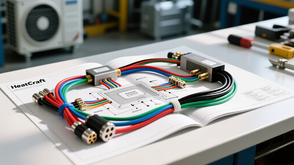
The Danger of Misinterpreting Transport Evaporator Schematics
Integrating commercial-grade HVAC and transport refrigeration components into heavy-duty vehicles requires a deep understanding of both automotive electrical systems and industrial refrigeration logic. When technicians pull up a heatcraft evaporator wiring diagram pdf to service a custom refrigerated box truck, a Ford Transit cutaway, or a Freightliner M2 mobile medical unit, they often assume standard 12V automotive logic applies. This is a critical error. Transport evaporators operate under extreme thermal cycling, high-vibration environments, and complex pulse-width modulation (PWM) controls that will quickly destroy standard automotive wiring if installed incorrectly.
This guide highlights the most common wiring mistakes, severe safety warnings, and SAE-compliant solutions for integrating and servicing heavy-duty evaporator units in commercial vehicle platforms.
Critical Safety Warnings for High-Amperage Defrost Circuits
The most dangerous circuit on any transport evaporator is the defrost heater. Unlike standard automotive rear-window defrosters that draw 10-15 amps, a commercial transport evaporator defrost heater can draw upwards of 35 to 50 amps at 12V/24V DC to melt heavy ice buildup on the coil fins.
Mistake 1: Bypassing the Thermal Limit Switch
Many technicians, frustrated by intermittent defrost failures caused by a failing bi-metal thermal limit switch, will bypass the switch to 'keep the truck running.' This is a severe fire hazard. If the defrost relay welds shut or the solid-state relay (SSR) fails closed, the heater will remain energized after the ice has melted. Without the thermal limit switch (typically rated to open at 165°F / 74°C), the heater will melt the ABS plastic evaporator housing, ignite the polyurethane insulation, and potentially cause a total vehicle loss. Never bypass OEM thermal safety limits.
Mistake 2: Undersizing the Defrost Power Feed and Relays
A 600W defrost heater on a 12V system draws roughly 50 amps. Using standard 10 AWG wire and a 40A ISO mini-relay will result in catastrophic voltage drop and relay failure. According to SAE J1128 standards for primary cable, you must use a minimum of 6 AWG cross-linked polyethylene (XLPE) wire for the main power feed to handle the continuous load and inrush current. Furthermore, you must use a heavy-duty ISO 280 high-current relay rated for at least 70A continuous, or preferably a solid-state contactor, to prevent contact welding.
PWM Blower Motor Signal Vulnerabilities (EMI and Routing)
Modern transport evaporators utilize Brushless DC (BLDC) blower motors controlled by a PWM signal from the vehicle's HVAC module or a standalone transport refrigeration unit (TRU) controller. A common mistake found when interpreting the schematic is routing the low-voltage PWM signal wire parallel to the high-current blower power wires or the defrost heater circuit.
High-current switching creates massive electromagnetic interference (EMI). If the 18 AWG PWM signal wire is not properly shielded, or if it is bundled with the 10 AWG blower power feed, inductive coupling will introduce voltage spikes into the signal line. The evaporator controller will misinterpret these spikes as erratic speed commands, causing the blower motor to surge, stall, or trigger a 'Motor Open Circuit' fault code on the J1939 CAN-bus network.
- The Fix: Always use shielded twisted-pair (STP) cable for PWM and tachometer feedback wires. Ground the shield drain wire at the controller end only to prevent ground loops.
- Routing Rule: Maintain a minimum 4-inch separation between low-voltage signal wires and high-amperage defrost/blower power feeds.
Heatcraft Evaporator Pinout and Wire Color Reference Chart
When working with the 6-pin Deutsch DT connector commonly found on heavy-duty truck evaporator assemblies, verifying the pinout against the specific diagram is crucial. Below is the standard reference for a 24V BLDC evaporator integration.
| Pin | Function | AWG Size | Wire Color | Technical Notes & Warnings |
|---|---|---|---|---|
| 1 | Blower Power (+) | 10 AWG | Red | Fused at 30A. Use XLPE insulation for heat resistance. |
| 2 | Blower Ground (-) | 10 AWG | Black | Must terminate at a dedicated chassis ground stud, not a sheet-metal screw. |
| 3 | PWM Control Signal | 18 AWG | Green (Shielded) | 0-5V or 0-10V duty cycle. Shield drain wire required. |
| 4 | Tach / RPM Feedback | 18 AWG | White | Open-collector output. Requires a 10k pull-up resistor at the ECU. |
| 5 | Thermistor Signal | 22 AWG | Yellow | 10k NTC. Twisted pair with Pin 6. Do not splice. |
| 6 | Thermistor Ground | 22 AWG | Blue | Sensor ground. Must share the same ground plane as the ECU. |
Thermistor Grounding and Voltage Drop Errors
The evaporator coil thermistor (typically a 10k NTC sensor) dictates the expansion valve cycling and defrost termination. A frequent mistake is splicing the thermistor ground wire into the nearest 12V accessory ground or using a corroded chassis ground point. Because the HVAC module measures the voltage drop across the thermistor to calculate temperature, even a minor voltage drop on the ground side will skew the reading.
For example, a mere 50mV drop on a poor ground connection can cause the ECU to read the evaporator coil as 8°F warmer than it actually is. This results in the compressor short-cycling, poor cabin cooling, and eventual coil freeze-up. The Mobile Air Climate Systems Association (MACS) strictly advises that all sensor grounds must be routed back to a dedicated, clean sensor ground bus or directly to the ECU ground pin to ensure absolute signal integrity.
Troubleshooting Decision Tree: Evaporator Electrical Faults
Use this structured diagnostic approach when facing common evaporator electrical failures in the field.
| Symptom | Probable Electrical Cause | Diagnostic Fix & Action Plan |
|---|---|---|
| Blower motor surges or pulses at low speeds. | EMI interference on the PWM signal wire from adjacent high-current wiring. | Inspect wire routing. Replace standard wire with shielded twisted pair (STP). Verify shield drain wire grounding. |
| Evaporator freezes solid; defrost never initiates. | Defrost relay coil failure or blown inline fusible link on the 6 AWG power feed. | Test relay coil resistance (should be 60-90 ohms). Check for 24V at the heater element during forced defrost mode. |
| ECU throws 'Evaporator Sensor Open Circuit' code. | Corrosion inside the Deutsch DT connector pushing the pin out of the housing. | Disconnect DT plug. Inspect for moisture ingress. Use a pin extraction tool to reseat the yellow/blue thermistor pins and apply dielectric grease. |
| Blower runs at 100% speed only; no speed control. | PWM signal wire broken or shorted to ground, causing the motor to default to fail-safe high mode. | Use an oscilloscope to verify the square wave PWM signal at the motor connector while adjusting the cab thermostat. |
Adhering to SAE and Heavy-Duty Standards
When modifying or repairing the wiring harness for a transport evaporator, technicians must adhere to heavy-duty circuit protection standards. Standard automotive blade fuses are insufficient for the vibration and thermal environments of a box truck or transit van engine bay and cargo area. Always utilize Mega-Val or ANL fuses for main feeds, and ensure all connectors are sealed to IP67 or IP6K9K standards to prevent water ingress from high-pressure truck washes. By respecting the specific requirements outlined in the manufacturer schematics and applying heavy-duty electrical principles, you can ensure reliable, safe, and efficient climate control and refrigeration for any commercial vehicle platform.