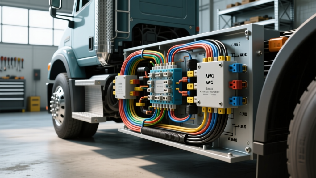
Understanding the Wiring Diagram Line and Load Disconnect in DC Systems
When upgrading the electrical architecture of a heavy-duty truck, commercial fleet vehicle, or Class A RV chassis, managing high-amperage direct current (DC) requires strict adherence to safety protocols. Unlike residential alternating current (AC) panels where the terms are ubiquitous, applying a wiring diagram line and load disconnect methodology to 12V and 24V automotive systems refers to the strategic isolation of the power source (Line) from the vehicle's distribution network and accessories (Load). This guide provides a comprehensive, practical installation procedure for integrating a heavy-duty battery disconnect solenoid or manual rotary switch into your vehicle's main power feed.
In automotive electrical theory, the 'Line' side represents the unswitched, raw DC voltage originating from the battery bank or alternator. The 'Load' side represents the downstream circuits, including the main fuse block, high-current inverters, and chassis accessories. Installing a master disconnect between these two points is not just a best practice; it is a critical safety requirement mandated by organizations like the ABYC E-11 Standard for marine and RV applications, and heavily recommended for commercial truck auxiliary power units (APUs).
Component Selection: Manual Rotary vs. Magnetic Latching Solenoid
Before cutting any wire, you must select the appropriate disconnect mechanism. For high-amperage applications (200A to 400A continuous), you have two primary options:
- Manual Rotary Disconnect (e.g., Cole Hersee 48124): A physically operated switch rated for heavy DC loads. Requires no control circuit but must be mounted in an accessible location.
- Continuous Duty Solenoid (e.g., Trombetta 114-1211-010): An electromagnetic switch operated remotely via a low-amperage dashboard toggle or ignition trigger. Ideal for mounting deep within an engine bay or battery compartment.
For this installation guide, we will focus on wiring a Continuous Duty Solenoid with a manual dashboard override, as it requires a more complex wiring diagram encompassing both the high-current line/load feed and the low-current control circuit.
Specification Chart: Heavy-Duty Disconnect Wiring Requirements
| System Parameter | Specification / Rating | Notes & Standards |
|---|---|---|
| Main Line/Load Cable | 2/0 AWG SAE J1128 Type SGT | Stranded copper, 600V rating. Capable of 200A continuous. |
| Control Circuit Wire | 10 AWG SAE J1128 Type GXL | Cross-linked polyethylene insulation for high engine bay temps. |
| Terminal Lugs | 3/8" Ring Terminal, Tin-Plated | Must match 2/0 AWG wire gauge. Avoid copper-aluminum bimetallic lugs. |
| Heat Shrink | 3/8" Adhesive-Lined Polyolefin | 3:1 shrink ratio. Adhesive melts to seal against moisture and corrosion. |
| Solenoid Coil Voltage | 12V DC (Continuous Duty) | Ensure 'Continuous' rating, not 'Intermittent' (starter style). |
| Terminal Torque Spec | 120 in-lbs (10 ft-lbs) | For 3/8"-16 steel or copper studs. Do not overtighten. |
Step-by-Step Installation: Wiring the Line and Load
Step 1: Prepping the Line Side (Battery to Solenoid)
- Safety First: Disconnect the negative (ground) battery cables first to eliminate the risk of a dead short while working on the positive Line side.
- Measure and Route: Measure the distance from the main battery bank positive post to the 'Line' terminal (usually marked 'BATT' or 'IN') on the solenoid. Add 6 inches for service loops and routing bends.
- Strip and Crimp: Strip 5/8" of insulation from the 2/0 AWG SGT cable. Insert the wire into the 3/8" tin-plated ring terminal. Use a hydraulic crimper equipped with a 3/8" hex die. The crimp should be uniform with no visible copper strands flaring outside the barrel.
- Seal the Connection: Slide a piece of 3/8" adhesive-lined heat shrink over the terminal barrel. Apply heat evenly until the adhesive purges slightly from the bottom edge, creating a watertight seal compliant with SAE J1171 ignition protection and moisture resistance standards.
- Terminate: Bolt the Line side lug to the solenoid's Line terminal. Torque to exactly 120 in-lbs. Apply a thin layer of dielectric grease over the exposed stud threads to prevent galvanic corrosion.
Step 2: Prepping the Load Side (Solenoid to Distribution)
- Route to Distribution: Run a second length of 2/0 AWG red cable from the solenoid's 'Load' terminal (marked 'AUX', 'OUT', or 'M') to the vehicle's main positive busbar or mega-fuse distribution block.
- Color Coding: While both Line and Load are positive DC, many master technicians use Red for the Line side and Black with a Red tracer (or pure Black if appropriately labeled) for the Load side to visually differentiate unswitched vs. switched power during future troubleshooting. If using black for the Load side, apply red heat shrink at both termination points to indicate positive polarity.
- Crimp and Seal: Repeat the hydraulic crimping and adhesive heat shrink process. Secure the Load side to the solenoid and torque to 120 in-lbs.
Step 3: Control Circuit Wiring (The Solenoid Trigger)
The high-current Line and Load circuit is now complete, but the solenoid requires a low-current signal to close the internal contactor. We will wire a manual dashboard toggle switch to control the disconnect.
- Ignition Source: Locate a 12V ignition-switched source in the cab (e.g., a 10A accessory circuit). Install an inline 10A ATO fuse holder within 6 inches of the power tap.
- Run Control Wire: Run 10 AWG GXL wire from the fused ignition source through the firewall to a heavy-duty SPST (Single Pole Single Throw) toggle switch on the dashboard.
- Switch to Solenoid: Run a second 10 AWG wire from the output side of the dashboard switch to the solenoid's 'I' (Ignition) or 'S' (Start/Signal) terminal.
- Ground the Coil: Connect the solenoid's 'G' (Ground) terminal to a clean, bare-metal chassis ground using a 10 AWG wire and a star washer to ensure a zero-resistance ground path.
Wiring Diagram: Line and Load Disconnect Pinout Reference
Refer to this terminal mapping when verifying your physical connections against your specific wiring diagram line and load disconnect schematic.
| Solenoid Terminal | Label | Wire Gauge | Destination / Function |
|---|---|---|---|
| Large Stud 1 | BATT / IN | 2/0 AWG (Red) | Line Side: Direct to Battery Bank Positive (+) |
| Large Stud 2 | AUX / OUT | 2/0 AWG (Red/Black) | Load Side: Direct to Main Fuse Block / Inverter Positive (+) |
| Small Spade 1 | I / SIG | 10 AWG (Yellow) | Control Signal: From Dashboard Toggle Switch Output |
| Small Spade 2 | G / GRD | 10 AWG (White/Black) | Coil Ground: Direct to Chassis Ground Point |
Troubleshooting Common Voltage Drop Issues
Even with a perfect wiring diagram line and load disconnect layout, poor installation practices can lead to severe voltage drop. In a 12V DC system, a voltage drop of just 0.5V across the disconnect switch can cause sensitive electronics, ECU modules, and inverters to trigger low-voltage fault codes.
Voltage Drop Testing Procedure
Do not use a multimeter to test resistance (Ohms) on a high-current circuit; the multimeter's internal battery cannot simulate real-world amperage. Instead, perform a live Voltage Drop test:
- Ensure the vehicle is running or a heavy load (like an inverter or winch) is actively drawing current through the disconnect.
- Set your digital multimeter to DC Volts.
- Place the red probe directly on the battery side of the Line terminal (the metal post, not the wire insulation).
- Place the black probe directly on the distribution side of the Load terminal.
- Read the voltage. According to the Littelfuse Heavy-Duty Switch Catalog and general automotive electrical standards, a healthy, clean connection should show a voltage drop of less than 0.10V (100mV).
Symptom-Cause-Fix Decision Tree
- Symptom: Voltage drop reads 0.45V under load.
- Cause: Oxidation on the copper strands inside the crimp barrel, or insufficient hydraulic crimp pressure.
- Fix: Cut off the terminal, clean the wire with contact cleaner, and re-crimp using a verified 3/8" hex die.
- Symptom: Solenoid clicks rapidly (chatters) but does not hold the Load side closed.
- Cause: Voltage drop on the 10 AWG control circuit wire, or a poor chassis ground on the 'G' terminal starving the coil of necessary amperage.
- Fix: Check the dashboard toggle switch contacts for pitting. Sand the chassis ground point down to bare, shiny metal and re-secure the star washer.
- Symptom: Disconnect becomes hot to the touch after 10 minutes of use.
- Cause: Terminal studs were not torqued to the 120 in-lbs specification, creating micro-arcing and high resistance at the mechanical joint.
- Fix: Disconnect power, allow the component to cool, inspect for melted heat shrink (indicating thermal damage), and re-torque or replace the solenoid if internal contacts are pitted.
Authoritative References
For further reading on heavy-duty DC electrical safety and installation standards, consult the following resources:
- ABYC E-11 Standard - American Boat and Yacht Council guidelines for AC and DC electrical systems, heavily referenced for RV and commercial truck battery disconnect requirements.
- SAE J1171 - Society of Automotive Engineers standard for ignition protection and moisture resistance in marine and heavy-duty engine bay electrical components.
- Littelfuse Heavy-Duty Switch Catalog - Manufacturer specifications for Cole Hersee rotary disconnects and master battery switches.