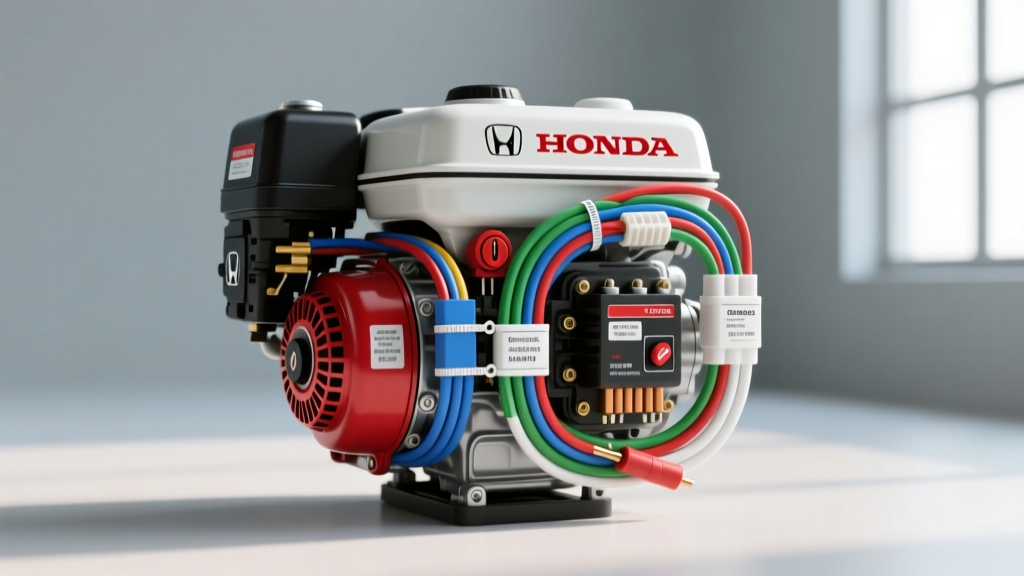
Introduction to the Honda GX390 Electrical System
The Honda GX390 is a legendary 389cc, 11.7-horsepower horizontal shaft engine widely used in off-road vehicles, custom go-karts, auxiliary power units, and heavy-duty pressure washers. Unlike modern automotive engines that rely on complex ECU pinouts, CAN-bus networks, and dozens of sensor inputs, the typical wiring diagram Honda GX390 setups require is refreshingly straightforward. However, simplicity does not mean you can ignore electrical fundamentals. Incorrect wiring can lead to fried stators, dead batteries, or dangerous short circuits.
This beginner-friendly guide breaks down the core electrical circuits of the GX390. Whether you are wiring a kill switch for a racing kart, integrating a 12V lighting coil for a generator build, or setting up an electric start system, understanding the underlying principles, wire gauges, and OEM color codes is essential for a safe and reliable build.
Core Circuit 1: Ignition and Kill Switch (Magneto)
The GX390 utilizes a transistorized magneto ignition system. This means the engine generates its own spark independently of any external 12V battery. The ignition coil is mounted directly outside the flywheel, and as the flywheel's embedded magnets pass the coil, they induce a magnetic field that collapses to send high voltage to the spark plug.
The 'kill switch' on a GX390 does not cut power to the coil; instead, it intentionally shorts the primary ignition circuit to ground. By grounding the primary wire, the magnetic field is bled off, preventing the high-voltage spark from forming at the plug. The OEM wire color for the ignition kill circuit is typically Black with a Yellow stripe (or solid Black on some aftermarket harnesses).
Wiring the Kill Switch
To wire a dashboard-mounted kill switch, you will route the Black/Yellow wire from the engine harness to one terminal of your toggle switch. The second terminal of the toggle switch must be connected to a clean, bare-metal chassis ground. When the switch is closed (OFF), the circuit grounds out, killing the spark. When the switch is open (ON), the circuit is broken, allowing the engine to run. Always use a minimum of 18 AWG wire for this circuit, as it carries very low current but requires reliable continuity.
Core Circuit 2: Charging Coil (Lighting Coil)
Many GX390 engines are equipped with an optional charging coil (often called a lighting coil) hidden under the flywheel. This stator coil generates Alternating Current (AC) as the flywheel spins. A common beginner mistake is attempting to wire this raw AC output directly to a 12V DC battery or LED light bar. Doing so will instantly destroy your electronics.
The raw output of the GX390 charging coil is roughly 14V to 28V AC at 3600 RPM, depending on the specific stator variant (usually rated between 3 Amps and 10 Amps). To use this power for automotive accessories or to maintain a 12V battery, you must pass the AC current through a bridge rectifier and voltage regulator. The OEM wire color for the charging coil output is typically Yellow or White.
Rectifier Integration
Connect the Yellow/White AC wire to the 'AC' input terminal on your rectifier. Connect the rectifier's 'DC+' output to your 12V battery positive terminal (with an inline 15A fuse) and the 'DC-' to the chassis ground. This converts the raw stator output into a clean, regulated 13.8V - 14.4V DC signal capable of charging a battery and powering auxiliary lights. For the AC wiring from the stator to the rectifier, use 16 AWG stranded copper wire to handle the amperage without voltage drop.
Core Circuit 3: Electric Start System
GX390 engines equipped with electric start feature a 12V DC starter motor mounted to the engine block. The starter motor draws a massive amount of current—typically 80 to 120 Amps during peak cranking. Because of this extreme amperage, you cannot run the starter directly from a dashboard key switch. You must use a heavy-duty starter solenoid (relay).
Solenoid Pinouts and Wire Gauges
According to the SAE J1128 Low Tension Primary Cable Standard, high-amperage starter circuits require thick, low-resistance cabling to prevent voltage drop and overheating. Use 6 AWG battery cable to connect the battery positive terminal to the solenoid's input stud, and another 6 AWG cable from the solenoid's output stud directly to the starter motor's terminal. The dashboard key switch will only send a low-amperage 12V trigger signal to the solenoid's 'S' (Start) terminal. This trigger wire should be 14 AWG. Ensure your engine block has a dedicated 8 AWG ground strap connecting it directly to the battery's negative terminal; relying on the engine mounting bolts to carry 120 Amps of return current will result in slow cranking and welded mounting hardware.
Honda GX390 Wiring Specifications & Wire Color Chart
| Circuit Function | OEM Wire Color | Recommended AWG | Voltage / Signal Type | Connector Type |
|---|---|---|---|---|
| Ignition Kill Switch | Black/Yellow | 18 AWG | Low Voltage (Ground Trigger) | Standard Spade / Weather-Pack |
| Charging Coil (Stator) | Yellow or White | 16 AWG | 14V-28V AC (Unregulated) | Weather-Pack 2-Way |
| Starter Motor Power | Red (Aftermarket) | 6 AWG | 12V DC (80A-120A Peak) | 5/16" Ring Terminal |
| Solenoid Trigger | Red/White | 14 AWG | 12V DC (Low Amp) | Standard Spade |
| Engine Ground Strap | Black | 8 AWG | Ground Return | 5/16" Ring Terminal |
Step-by-Step Troubleshooting for Beginners
When an engine swap or auxiliary build fails to start, beginners often replace parts blindly. Use a digital multimeter to diagnose the actual failure point.
Testing the Kill Switch Continuity
If your GX390 has no spark, the kill circuit may be permanently grounded. Set your multimeter to the Ohms (Ω) setting. Place one probe on the Black/Yellow kill wire and the other on a clean metal part of the engine block. With the kill switch in the 'RUN' position, the meter should read 'OL' (Open Loop / Infinite resistance). If it reads near 0.00 ohms, your switch is faulty, or the wire is pinched against the chassis, constantly grounding out your ignition coil.
Verifying the Charging Coil Output
If your 12V battery keeps dying despite having a charging coil, test the stator. Disconnect the Yellow stator wire from the rectifier. Set your multimeter to AC Volts. Start the engine and run it at roughly 3000 RPM. Probe the Yellow wire and the engine block. You should see between 14V and 28V AC. If you read 0V AC, the stator coil is burnt out or the flywheel key has sheared, altering the magneto timing. For deeper diagnostic procedures, refer to the Honda Power Equipment OEM Manuals.
Best Practices for GX390 Engine Swaps
When integrating a GX390 into a vehicle chassis (such as a sand rail, UTV, or custom kart), environmental protection is critical. The OEM Honda harness is designed for open-air utility equipment, not the mud, water, and vibration of off-road racing. Always upgrade to Deutsch DT or Weather-Pack sealed connectors for any wire that crosses from the engine to the chassis. Apply dielectric grease to all spark plug boots and coil connections to prevent moisture ingress, which can cause the high-voltage spark to arc to the engine block instead of jumping the plug gap. Finally, always route your high-voltage spark plug wire away from the Yellow charging coil wire to prevent electromagnetic interference (EMI) from damaging your rectifier or causing erratic voltage regulation.