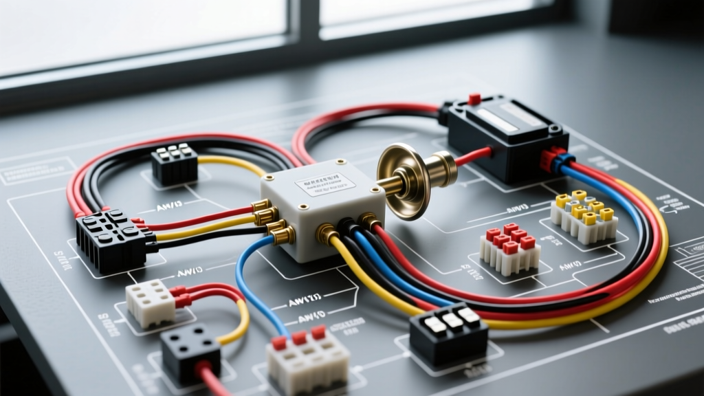
Introduction to Horn Blaster Electrical Systems
Installing a high-decibel air horn kit requires more than just bolting a compressor to the chassis and running a single wire to the battery. A proper horn blaster wiring diagram must account for high inrush currents, voltage drop over long chassis runs, and the delicate logic of modern Body Control Modules (BCMs). Whether you are wiring a Kleinn train horn kit, a Viair 480C dual-compressor setup, or a generic 12V solenoid-valve system, the electrical foundation dictates the reliability of the entire system. This guide breaks down the exact cost of materials, the specialized automotive tooling required for a factory-grade installation, and the technical specifications necessary to prevent melted pressure switches and fried BCMs.
Core Circuit Logic & OEM Trigger Integration
The most common failure point in aftermarket air horn installations is the integration with the vehicle's OEM horn trigger. Post-2000 vehicles rarely use a direct 12V+ wire from the steering wheel clock spring to the horn. Instead, the horn button acts as a ground-switched input to the BCM or Steering Wheel Control Module (SWCM). The BCM then triggers a factory horn relay.
Intercepting the OEM Signal
To properly wire your horn blaster kit, you must intercept the 12V+ trigger at the factory horn relay output or directly at the OEM horn connector. This 12V+ signal will serve as the trigger for Pin 86 on your aftermarket heavy-duty relay. If your vehicle uses a ground-switched trigger at the horn location, you must use a 5-pin Bosch-style relay to invert the logic, ensuring the aftermarket compressor relay only receives a 12V+ signal when the horn button is pressed. Never tap directly into the BCM's low-current ground trigger wire; the voltage flyback from an aftermarket relay coil can destroy the BCM's internal transistor.
Bill of Materials (BOM) & Cost Breakdown
Building a reliable horn blaster wiring harness from scratch is often superior to using the pre-packaged, undersized wiring looms included with budget air horn kits. Below is a professional-grade BOM based on SAE J1128 primary cable standards.
| Component | Specification | Est. Cost |
|---|---|---|
| Primary Power Wire | 8 AWG SAE J1128 (Red, 15ft) | $28.00 |
| Trigger & Ground Wire | 14 AWG TXL Cross-linked (Black/White) | $12.00 |
| Heavy Duty Relay | Bosch-style 40A/50A (SPST or SPDT) | $14.00 |
| Overcurrent Protection | ANL Fuse Block + 50A ANL Fuse | $22.00 |
| Terminals & Connectors | Weather-Pack / Metri-Pack Sealed Terminals | $18.00 |
| Insulation & Protection | 3M Adhesive-Lined Heat Shrink & Split Loom | $24.00 |
| Flyback Diode | 1N4001 Rectifier Diode (Solenoid Protection) | $0.15 |
| Total Material Cost | Professional-Grade Harness | ~$118.15 |
Wire Gauge & Voltage Drop Specifications
Air compressors, such as the Viair 400-series, can draw upwards of 45 amps under peak load (0 PSI). If you mount the compressor in the rear cargo area and run power from the engine bay battery, you are pushing high current over 15 to 20 feet of wire. According to Viair Corporation's technical guidelines, using 10 AWG or 12 AWG wire for a rear-mounted compressor will result in severe voltage drop, causing the compressor to overheat, draw even more amperage, and eventually trip the thermal breaker.
- 8 AWG Wire: Mandatory for the main power feed (Pin 30 to Pin 87) on runs exceeding 10 feet. Rated for ~50A in chassis wiring applications.
- 14 AWG Wire: Sufficient for the relay coil trigger (Pin 86), ground circuits (Pin 85), and solenoid valve actuation wires. Solenoid valves typically draw 15A-20A inrush, which 14 AWG handles safely over short distances.
Essential Tool Requirements for a Factory-Grade Install
The difference between a harness that lasts a decade and one that causes an electrical fire lies in the termination method. Twisting wires and wrapping them in electrical tape is unacceptable in high-vibration, high-temperature automotive environments. Below is the required tooling matrix for proper harness fabrication.
| Tool | Purpose | Investment Tier |
|---|---|---|
| Automatic Wire Stripper (e.g., Knipex) | Prevents nicking copper strands on 8-14 AWG wire | $45 - $65 |
| Open/Barrel Crimp Tool (e.g., Delphi/IWISS) | Creates gas-tight, cold-weld crimps on sealed terminals | $35 - $80 |
| Heat Gun with Reflector Nozzle | Evenly shrinks adhesive-lined heat shrink without scorching | $40 - $120 |
| Digital Multimeter (e.g., Innova 3320) | Verifies OEM trigger logic and checks for voltage drop | $25 - $50 |
Crimping vs. Soldering in High-Vibration Zones
While soldering is often touted as the gold standard in household electronics, it is a liability in automotive engine bays and chassis mounts. Solder creates a rigid joint. When subjected to the constant vibration of a diesel engine or a truck frame, the boundary where the stiff solder meets the flexible copper wire becomes a stress riser, leading to work-hardening and eventual wire fracture. Furthermore, solder can wick up into the wire insulation via capillary action, reducing flexibility. Painless Performance Products and OEM manufacturers mandate the use of mechanical crimps with open-barrel or closed-barrel terminals, sealed with adhesive-lined heat shrink to prevent moisture intrusion and corrosion.
Solenoid Valve Actuation & Flyback Diodes
Many Horn Blaster kits utilize a remote air tank and a 1/2-inch or 3/4-inch solenoid valve to release the air, rather than running the compressor directly. When you release the horn button, the circuit to the solenoid valve opens. The collapsing magnetic field inside the solenoid's coil generates a massive reverse voltage spike (Back EMF), sometimes exceeding 100V for a fraction of a millisecond. If this spike travels back through the trigger wire, it can arc the contacts inside your steering wheel horn button or destroy the BCM's horn driver circuit.
The Fix: Solder a standard 1N4001 flyback diode directly across the solenoid valve's terminals. The cathode (striped end) must point toward the 12V+ source, and the anode toward the ground/trigger. This $0.15 component creates a localized loop for the Back EMF to dissipate safely, protecting your vehicle's expensive OEM electronics.
Real-World Troubleshooting & Failure Modes
1. Pressure Switch Melting
Symptom: The compressor runs continuously, or the plastic housing of the pressure switch melts.
Cause: The pressure switch was wired in series with the compressor's main power feed. Compressor inrush current (40A+) exceeds the pressure switch's 20A contact rating, causing internal arcing that welds the contacts shut.
Solution: The pressure switch must only carry the low-current load of the relay coil (Pin 86). Wire the main battery power through a 50A ANL fuse directly to the heavy-duty relay (Pin 30), and route the relay's output (Pin 87) to the compressor.
2. Compressor Sluggishness & Thermal Tripping
Symptom: Compressor takes twice as long to fill the tank and frequently shuts off due to thermal overload.
Cause: Voltage drop caused by undersized wire or poor ground connections. A compressor receiving 10.5V instead of 12.5V will draw higher amperage to produce the same mechanical work, generating excess heat.
Solution: Upgrade the power and ground paths to 8 AWG wire. Ensure the ground terminal is bolted directly to bare, unpainted chassis metal using a star washer to bite through the zinc coating or primer.
Summary
Executing a flawless horn blaster wiring diagram requires a methodical approach to cost allocation and tooling. By investing approximately $120 in SAE-spec wire, ANL fusing, and proper crimping tools, you eliminate the risk of electrical fires and BCM damage. Understanding the physics of inrush current, voltage drop, and inductive flyback ensures your air horn system operates reliably, delivering maximum decibel output every time you press the wheel.