Why the OEM Charging System Fails on Overland JKs
The 3.6L Pentastar-equipped Jeep Wrangler JK (2012-2018) is a cornerstone of the overlanding and off-road community. However, the factory 160-amp or 180-amp alternator was never designed to support the massive electrical loads of modern expedition builds. When you add a 12,000-lb winch (drawing up to 350 amps under peak load), a dual-battery management system, a 60-liter 12V compressor fridge, and high-draw LED light bars, the OEM charging system quickly bottlenecks. This leads to chronic under-voltage conditions, premature battery sulfation, and eventually, a stranded vehicle.
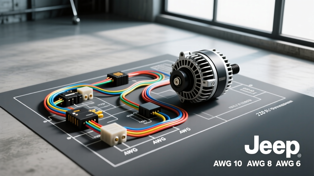
Upgrading to a high-output 220-amp alternator is the most reliable solution. However, simply bolting on a larger alternator without upgrading the supporting wiring harness is a recipe for melted insulation, voltage drop, and electrical fires. This practical how-to guide and wiring diagram for 220 amp alternator installations will walk you through the exact AWG requirements, PCM pinout configurations, and crimping standards necessary to safely handle 220 amps of continuous charging current in a JK Wrangler.
Pre-Installation Safety and Tool Requirements
Before touching any electrical components, safety and proper tooling are non-negotiable. Working with 220 amps of DC current requires adherence to SAE J1128 standards for battery cable specifications and insulation ratings.
- Safety First: Disconnect the negative battery terminal and isolate it. Wait at least 10 minutes for the airbag system capacitors to discharge.
- Crimping Tools: Do not use hammer crimpers or pliers. Use a dedicated hexagonal-die hydraulic or ratcheting crimper designed for 1/0 AWG copper lugs.
- Heat Shrink: Use only 3:1 shrink ratio, adhesive-lined (marine-grade) dual-wall heat shrink. Standard PVC shrink will not seal out moisture and will lead to green rot (copper oxidation) inside the lug.
- Wire Strippers: Use a specialized fine-strand wire stripper to avoid nicking the copper strands, which reduces the overall ampacity of the cable.
- Multimeter: A True-RMS digital multimeter capable of measuring millivolt (mV) drops is required for post-installation testing.
Decoding the Wiring Diagram for 220 Amp Upgrades
When referencing a comprehensive wiring diagram for 220 amp applications, the circuit is divided into two distinct systems: the High-Current Charge Circuit and the PCM Control/Sense Circuit. Understanding the interaction between these two circuits is critical for a successful installation.
The High-Current Charge Circuit
The OEM JK positive charge wire is typically 4 AWG, rated for roughly 160-180 amps depending on ambient under-hood temperatures. Pushing 220 amps through 4 AWG wire over the 4-foot run from the alternator B+ terminal to the Power Distribution Center (PDC) or battery will result in severe voltage drop and excessive heat generation. The wiring diagram for 220 amp systems mandates an upgrade to 1/0 AWG (0 AWG) fine-strand copper welding cable. This reduces resistance and ensures the full 14.2V - 14.4V reaches the battery bank.
The PCM Sense and Exciter Circuit
The JK's 3.6L PCM uses a 2-pin connector to control the alternator. Pin A is the 'Sense' wire, and Pin B is the 'Field/Exciter' wire. The OEM sense wire is a thin 18 AWG conductor routed through the engine harness. Because a 220-amp alternator is highly sensitive to voltage reference, any voltage drop across this thin 18 AWG wire will trick the PCM into overcharging the battery to compensate. To fix this, the sense wire must be upgraded to 12 AWG and routed directly to the positive battery post or main busbar, bypassing the OEM harness resistance.
Step-by-Step Installation Guide
Step 1: OEM Removal and Bracket Inspection
- Remove the serpentine belt using a 15mm wrench on the automatic tensioner.
- Disconnect the 2-pin PCM pigtail and the B+ positive nut (13mm).
- Remove the two M10 x 1.5 alternator mounting bolts. Insider Tip: Inspect the aluminum mounting bracket for galvanic corrosion. Clean it with a wire brush to ensure a perfect ground path for the alternator case.
Step 2: Fabricating the 1/0 AWG Charge Cable
- Measure the distance from the alternator B+ post to the positive battery terminal or main fuse block. Add 6 inches for routing slack.
- Cut the 1/0 AWG fine-strand copper cable.
- Strip exactly 5/8 inch of insulation. Twist the strands tightly to prevent fraying.
- Insert the wire into a 1/0 AWG to 5/16' stud copper ring terminal (for the alternator side) and a 1/0 AWG to 3/8' stud terminal (for the battery side).
- Crimp using a hexagonal die. Apply adhesive-lined heat shrink, ensuring the adhesive oozes slightly from the edges to guarantee a waterproof seal.
- Wrap the entire length of the 1/0 AWG cable in split-loom tubing and Tesa tape to protect against abrasion from the engine block and belt routing.
Step 3: Upgrading the PCM Sense Pigtail
According to Mopar TechAuthority service documentation, the alternator connector is a sealed Delphi Metri-Pack 280 series. You will need a replacement pigtail (Mopar Part #68086115AA or equivalent).
- Cut the OEM pigtail 4 inches from the connector.
- Solder and heat-shrink a 12 AWG primary wire to the Sense pin (Cavity 1).
- Solder and heat-shrink a 14 AWG primary wire to the Field pin (Cavity 2).
- Route the 12 AWG Sense wire directly to the positive battery terminal, securing it with an inline 30-amp MAXI fuse placed within 6 inches of the battery post.
Step 4: Final Routing and Torque Specifications
Proper torque is vital to prevent arcing at high amperages. Refer to the table below for exact specifications:
| Connection Point | Hardware | Torque Specification |
|---|---|---|
| Alternator B+ Terminal | M8 x 1.25 Flange Nut | 12 Nm (106 in-lb) |
| Alternator Mounting Bolts | M10 x 1.5 Flange Bolt | 41 Nm (30 lb-ft) |
| Battery Positive Terminal | M8 or 3/8' Post Nut | 10 Nm (89 in-lb) |
Technical Reference: PCM Pinout and Wire Codes
When troubleshooting or verifying your wiring diagram for 220 amp alternator control circuits, use this pinout reference for the 2012-2018 3.6L Pentastar PCM C2 Connector:
| Connector Cavity | Function | OEM Wire Color | Upgrade Wire Spec |
|---|---|---|---|
| Pin 1 (Sense) | Battery Voltage Reference | Dark Green / White Stripe | 12 AWG (Red) w/ 30A Fuse |
| Pin 2 (Field) | PWM Ground Control / Exciter | Dark Blue / Yellow Stripe | 14 AWG (Blue) |
Note: The PCM uses Pulse Width Modulation (PWM) on the Field wire to control the internal voltage regulator. High-output alternators from reputable manufacturers like DC Power Inc are designed to interpret this OEM PWM signal seamlessly without requiring external bypass regulators.
Post-Installation Voltage Drop Testing
Never assume a 220-amp installation is successful simply because the battery light turns off. You must perform a voltage drop test under load to verify the integrity of your crimps and wire sizing.
- Reconnect the battery and start the engine.
- Turn on all high-draw accessories (headlights, blower motor on high, rear defroster, and auxiliary lights) to force the PCM to command the alternator to maximum output.
- Set your multimeter to DC Millivolts (mV).
- Place the red probe on the alternator B+ post (the metal stud, not the nut) and the black probe on the positive battery post.
- Acceptable Reading: Less than 200 mV (0.2V). If you read 0.3V or higher, you have a bad crimp, undersized wire, or corrosion at the terminal.
- Repeat the test on the ground side: Red probe on the alternator case, black probe on the negative battery post. The reading must be under 100 mV (0.1V). If it is higher, clean the engine block grounding strap and the alternator mounting bracket.
Common Failure Modes and Troubleshooting
Symptom: Alternator whines and battery voltage fluctuates between 12.8V and 15.5V.
Cause: The PCM Sense wire was not upgraded or is reading voltage from the PDC instead of the battery post. The 220A regulator is 'hunting' for the correct voltage reference.
Fix: Reroute the 12 AWG sense wire directly to the positive battery terminal with a dedicated inline fuse.
Symptom: 1/0 AWG charge cable becomes hot to the touch after 10 minutes of winching.
Cause: Poor crimp connection at the ring terminal creating localized resistance, or the cable is routed too close to the exhaust manifold, degrading the copper conductivity.
Fix: Cut off the lug, inspect for copper oxidation, re-crimp with a proper hex-die tool, and reroute away from heat sources using a thermal sleeve.
By strictly following this wiring diagram for 220 amp configurations and adhering to SAE crimping standards, your JK Wrangler will possess a bulletproof charging system capable of handling the most extreme expedition electrical demands.