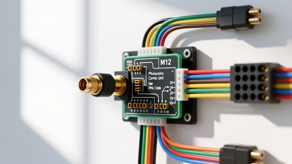
Introduction to Automotive Photoelectric Sensor Integration
In modern vehicle architectures, particularly within Electric Vehicle (EV) thermal management systems, automated manual transmissions (AMTs), and steer-by-wire optical encoders, the photoelectric sensor wiring diagram represents a critical interface between physical mechanical states and digital ECU logic. Unlike Hall-effect sensors, which rely on magnetic fields and are susceptible to interference from high-current EV inverters and electric power steering (EPS) motors, photoelectric (optical) sensors utilize modulated infrared (IR) light to detect object presence, fluid flow, or rotational encoding. This immunity to electromagnetic interference (EMI) makes them indispensable in high-noise automotive environments.
However, integrating these sensors into 12V or 24V vehicle networks requires meticulous attention to signal conditioning, load dump protection, and grounding topologies. This advanced technical deep dive dissects the OEM-level wiring schematics, M12 connector pinouts, and ECU optoisolation circuits required to deploy photoelectric sensors reliably in harsh under-hood and chassis environments.
M12 Connector Pinout and 22 AWG Wire Specifications
Automotive-grade photoelectric sensors typically utilize the M12 A-coded circular connector, governed by IEC 61076-2-101 standards, ensuring IP67/IP69K ingress protection against high-pressure washdowns and fluid ingress. The standard 4-wire configuration provides independent power, ground, and dual complementary outputs (Light-ON / Dark-ON).
4-Wire M12 Automotive Pinout Reference Table
| Pin | Wire Color | AWG / Metric | Function | ECU Interface Notes |
|---|---|---|---|---|
| 1 | Brown (BN) | 22 AWG (0.34 mm²) | +VDC (12V/24V) | Requires TVS diode for ISO 7637-2 load dump protection. |
| 2 | White (WH) | 22 AWG (0.34 mm²) | Output 1 (Signal A) | Primary digital input to ECU GPIO (e.g., Light-ON). |
| 3 | Blue (BU) | 22 AWG (0.34 mm²) | 0V (Ground) | Must tie to sensor logic ground, NOT chassis ground. |
| 4 | Black (BK) | 22 AWG (0.34 mm²) | Output 2 (Signal B) | Complementary input (e.g., Dark-ON) for plausibility checks. |
Note: For high-vibration environments such as heavy-duty commercial truck shift rails, ETFE (Tefzel) insulated 22 AWG wire per SAE J1128 is mandated to prevent insulation cracking at the crimp barrel.
PNP vs. NPN Logic in Vehicle Networks
When reviewing a photoelectric sensor wiring diagram for automotive applications, determining the output transistor topology is paramount. Vehicle ECUs are highly specific regarding whether they expect a sourcing (PNP) or sinking (NPN) signal.
PNP (Sourcing) Architecture
Standard in European heavy-duty platforms (24V systems) and most modern passenger EVs. In a PNP configuration, the sensor switches the positive supply voltage to the output pin. The ECU GPIO pin is configured with an internal pull-down resistor to ground. When the photoelectric beam is broken or reflected, the PNP transistor conducts, pulling the ECU pin high to battery voltage.
NPN (Sinking) Architecture
More common in legacy Asian 12V architectures. The sensor switches the ground connection. The ECU GPIO requires an internal or external pull-up resistor to the 5V or 12V logic rail. When triggered, the NPN transistor pulls the ECU pin low. NPN is generally less preferred in modern automotive design due to the risk of false-triggering if a short-to-ground occurs in the wiring harness.
ECU Signal Conditioning and Optoisolation
Directly wiring a 12V/24V photoelectric sensor output into an automotive microcontroller (such as an NXP S32G or Infineon AURIX) is a critical failure risk. Voltage transients, ground loops, and inductive kickback from nearby solenoids can destroy the ECU's internal ADC/GPIO logic gates. A robust wiring diagram must include an optoisolation stage.
Designing the Optocoupler Interface
To isolate the sensor's power domain from the ECU's sensitive 3.3V logic domain, an automotive-grade optocoupler (e.g., Vishay VO618A) is utilized. Below is the design logic for the input-side current-limiting resistor (R1) for a 24V heavy-duty truck system:
- Supply Voltage (Vs): 24V (nominal), up to 32V during charging.
- Optocoupler Forward Voltage (Vf): 1.2V typical.
- Desired Forward Current (If): 10mA (ensures reliable CTR over temperature degradation).
- Calculation: R1 = (Vs - Vf) / If = (24V - 1.2V) / 0.01A = 2280 Ω.
- Component Selection: Use a standard 2.2 kΩ, 1/4W resistor with a 1% tolerance, paired with a reverse-bias protection diode (e.g., 1N4148) in parallel with the optocoupler LED to protect against negative voltage transients.
For comprehensive protection against ISO 7637-2 Pulse 5 (Load Dump), a bidirectional TVS diode (such as the Littlefuse SMAJ24CA) must be placed on the Brown (+VDC) wire immediately at the sensor connector or ECU bulkhead.
EMI Shielding and Harness Routing
While photoelectric sensors themselves are immune to magnetic fields, the wiring harness carrying the 12V/24V square-wave output back to the ECU acts as an antenna. In EV platforms, the high-frequency switching of the traction inverter (often 10-20 kHz with high dv/dt) can induce common-mode noise onto unshielded sensor wires, causing the ECU to register 'ghost' pulses.
Shielding Best Practices
- Twisted Pair: The Signal (White) and Ground (Blue) wires must be twisted at a rate of 6-8 twists per inch to cancel out induced differential noise.
- Braided Shield: A tinned copper braid with a minimum 85% optical coverage must encapsulate the twisted pair.
- 360-Degree Termination: According to Bosch Automotive Electrics EMC guidelines, the shield drain wire must never be pigtailed to ground. Pigtailing creates an inductive loop that renders the shield useless at high frequencies. Instead, the shield must be clamped using a 360-degree shield ring connector directly to the ECU metal chassis bulkhead.
Troubleshooting Decision Tree
When diagnosing faults related to the photoelectric sensor wiring diagram, technicians must move beyond simple continuity checks and evaluate signal integrity.
| Symptom | Probable Root Cause | Advanced Diagnostic Fix |
|---|---|---|
| Erratic triggering near EV inverter | Common-mode EMI coupling on signal wire | Verify 360-degree shield clamp; check for missing shield drain wire. |
| Sensor output stuck HIGH | Optocoupler CTR degradation or shorted TVS | Measure voltage across optocoupler pins 1-2; replace if Vf is 0V. |
| Delayed response time (ms lag) | Capacitive loading from excessive wire length | Reduce wire length or add a 1kΩ pull-down resistor at the ECU pin. |
| Sensor fails in high heat (under-hood) | IR LED thermal drift or lens fogging | Check sensor ambient rating; clean optical window with isopropyl alcohol. |
Summary
Integrating a photoelectric sensor into an automotive ECU requires far more than matching wire colors. By adhering to strict M12 pinout standards, implementing rigorous optoisolation, and executing flawless EMC shielding terminations, engineers and master technicians can ensure that optical sensor data remains pristine, even in the most electrically hostile vehicle environments.