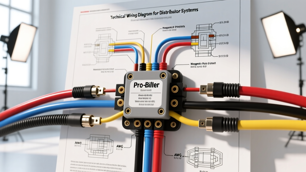
Introduction to MSD Capacitive Discharge Wiring Architecture
Upgrading from a factory points-style or HEI ignition to a capacitive discharge system requires a precise understanding of the electrical architecture. When referencing a wiring diagram for MSD distributor configurations, technicians must account for the high-voltage, multiple-spark output that defines MSD (Multiple Spark Discharge) technology. Unlike inductive systems that rely on the coil's primary winding collapse, MSD ignition controls utilize a step-up transformer and a bank of capacitors to deliver a series of sparks across the plug gap. This fundamental difference dictates strict adherence to wire gauge specifications, shielding protocols, and ground plane management.
According to MSD Performance Official Documentation, improper routing or undersized power wires are the leading causes of module failure and erratic high-RPM misfires. This technical specification reference outlines the exact pinouts, AWG requirements, and integration schematics for pairing MSD Pro-Billet, Ready-to-Run, and EFI distributors with 6-Series and 7-Series ignition controls.
MSD Distributor Harness Color Code & Pinout Specifications
MSD distributors utilize specific flying lead harnesses terminated with Weathertight or bare bullet connectors. The wire color codes are standardized across the industry, but the internal trigger mechanism (Magnetic Pickup vs. Hall Effect) dictates how these wires interface with the ignition control box. Per SAE International J1128 Primary Wire Standards, signal wires must be rated for high-temperature engine bay environments and possess adequate dielectric strength to prevent cross-talk.
| Wire Color | AWG Size | Function / Signal Type | Termination & Routing Notes |
|---|---|---|---|
| Violet | 18 AWG | Magnetic Pickup Positive (+) | Twisted pair with Green. Route away from alternator. |
| Green | 18 AWG | Magnetic Pickup Negative (-) | Twisted pair with Violet. Do not ground to chassis. |
| Red | 18 AWG | Hall Effect 12V Switched Power | Connect to clean 12V ignition-run source only. |
| Black | 18 AWG | Hall Effect Sensor Ground | Terminate at dedicated ECU or ignition box ground. |
| White | 18 AWG | Hall Effect Signal Output | 12V Square wave. Shield if running near EFI injectors. |
Magnetic Pickup Integration (Pro-Billet Distributors)
The MSD Pro-Billet distributor (e.g., PN 8360 for Small Block Chevy) utilizes a magnetic pickup coil to generate an AC voltage signal as the reluctor wheel teeth pass the sensor. When consulting the wiring diagram for MSD distributor magnetic setups, the Violet and Green wires must be connected directly to the corresponding Magnetic Pickup inputs on the MSD 6AL or 6A ignition box.
Polarity and Phasing Criticality
Unlike Hall Effect sensors, magnetic pickups generate an alternating current (AC) sine wave. The polarity of the Violet (Positive) and Green (Negative) wires is absolutely critical. If reversed, the ignition box will trigger on the trailing edge of the reluctor tooth rather than the leading edge. This results in severe timing retardation, backfiring through the carburetor, and potential engine damage. To verify polarity without an oscilloscope, use a digital multimeter set to AC Volts while cranking the engine; the voltage should read between 1.5V and 4.0V AC. Furthermore, the Violet and Green wires must be twisted together at a rate of at least four twists per foot to cancel out electromagnetic interference (EMI) generated by the alternator and ignition secondary wires.
Hall Effect Integration (Ready-to-Run & EFI Distributors)
MSD Hall Effect distributors output a digital 12V square wave, making them ideal for modern EFI systems (such as Holley Sniper or Megasquirt) that require a clean, noise-free tachometer signal. The wiring diagram for MSD distributor Hall Effect setups involves three wires: Red (12V Power), Black (Ground), and White (Signal).
Square Wave Signal Routing
The White signal wire outputs a 0-12V square wave that transitions precisely as the shutter wheel crosses the Hall Effect sensor. Because this is a high-impedance digital signal, it is highly susceptible to capacitive coupling from adjacent high-current wires. The White wire must never be bundled with injector harnesses, fuel pump relays, or the MSD Orange/Black coil wires. When interfacing with an EFI ECU, verify whether the ECU input requires a pull-up or pull-down resistor; while the MSD Hall Effect module actively drives the signal high and low, some older OEM ECUs require a 1K-ohm pull-up resistor to stabilize the 12V logic level.
Ignition Control Box Power and Ground Specifications
The most common point of failure in any MSD installation is inadequate power delivery. The MSD 6-Series ignition box draws up to 14 amps continuously and can spike over 30 amps during high-RPM, high-load capacitive discharge cycles. Summit Racing Technical Articles frequently highlight voltage drop as the primary culprit for weak high-RPM spark.
- Main Power (Red Wire): Must be a minimum of 8 AWG stranded copper wire, routed directly to the positive battery terminal or a dedicated high-amperage distribution stud. An inline 60A ANL fuse or marine-grade circuit breaker is mandatory within 18 inches of the battery connection.
- Main Ground (Black Wire): Must be a minimum of 8 AWG stranded copper. Terminate using a heavy-duty copper ring terminal, secured to bare, unpainted chassis metal or the engine block. Use a star washer to bite through any surface oxidation. The voltage drop across the ground connection should measure less than 0.05V under cranking loads.
- Switched 12V (Thin Red Wire): This 18 AWG wire triggers the internal circuitry of the MSD box. It must be connected to a true 12V "Run/Start" ignition source. Do not connect this to the negative side of an ignition coil or a ballast resistor bypass circuit, as voltage fluctuations will cause the box to reset.
Ignition Coil Interface and Ballast Resistor Bypass
When wiring the MSD ignition box to the ignition coil (such as the MSD Blaster 2, PN 8202), the Orange wire connects to the Coil Positive (+) terminal, and the Black wire connects to the Coil Negative (-) terminal. These wires carry the high-frequency, high-voltage primary pulses and should be kept as short as possible, ideally under 12 inches.
Eliminating the Factory Ballast Resistor
Vehicles originally equipped with points-style ignitions (e.g., classic Mopar, GM, and Ford applications) utilize a ballast resistor or a resistance wire in the factory harness to drop the voltage to the coil to roughly 7-9V during normal running conditions. Because the MSD ignition box generates its own high-voltage capacitive discharge (up to 500+ volts to the coil primary), the factory ballast resistor must be completely bypassed or removed. Leaving the ballast resistor in the circuit will starve the MSD box's internal step-up transformer, resulting in a severe loss of spark energy above 4,000 RPM and eventual overheating of the ignition control module.
Tachometer Signal Routing and EFI Interfacing
The MSD ignition box features a dedicated Tachometer Output wire (typically White or Violet depending on the specific PN, but standard 6AL uses a dedicated Tach terminal). This output provides a 12V square wave pulse, capable of sinking up to 200mA. While this easily drives standard aftermarket analog tachometers (like AutoMeter or Stewart-Warner), it can damage the sensitive logic inputs of modern engine management systems.
When wiring the MSD tach signal to an EFI system or a modern digital dash, it is highly recommended to install an MSD Tach Filter (PN 8920) or an opto-isolator circuit. This prevents high-frequency EMI from the ignition secondary from back-feeding into the ECU's tach input, which can cause erratic fuel injector pulse-width calculations and idle surge.
Common Wiring Failure Modes & Diagnostics
Even with a perfect wiring diagram for MSD distributor implementation, environmental factors and vibration can induce faults. Use the following diagnostic parameters to troubleshoot the system:
- Erratic Timing at High RPM: Usually caused by EMI interference on the Violet/Green magnetic pickup wires. Check for broken shielding, improper routing near the alternator, or loose bullet connectors. Verify the twisted pair integrity.
- Engine Dies When Headlights/Turn Signals Activate: Indicates a severe ground plane issue. The MSD box is sharing a ground path with high-draw accessories. Relocate the 8 AWG MSD ground to a dedicated, clean engine block stud.
- No Spark, but Box LED Illuminates: Test the coil primary wires (Orange and Black) for continuity. Check the coil itself; an open primary winding or a shorted secondary winding will prevent the MSD box from completing the capacitive discharge cycle.
- Backfiring Through the Carburetor on Startup: Verify the Violet and Green wire polarity. If confirmed correct, check the rotor phasing. The rotor tip must align with the distributor cap terminal at approximately 15 degrees BTDC during cranking. Improper mechanical phasing cannot be fixed via wiring adjustments and requires adjusting the distributor hold-down or using an adjustable rotor.
By adhering strictly to these AWG specifications, routing protocols, and signal conditioning requirements, the MSD capacitive discharge system will deliver consistent, high-energy spark across the entire RPM range, maximizing combustion efficiency and engine reliability.