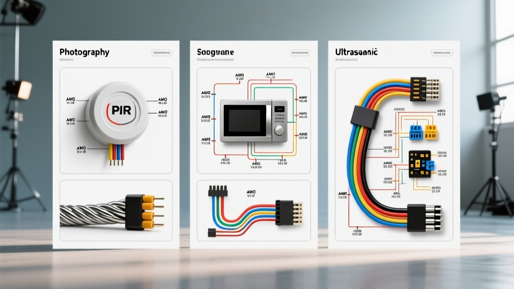
The Role of Volumetric Sensors in Vehicle Security
When designing or upgrading a vehicle security system, interior volumetric monitoring is critical for detecting unauthorized entry through broken glass or sunroofs. Selecting the correct sensor technology and understanding the underlying motion sensor wiring diagram is essential to prevent phantom alarms, battery drain, and electromagnetic interference (EMI). Unlike standard door pin switches that only monitor perimeter entry points, motion sensors create a three-dimensional detection field inside the cabin. This guide compares the three primary automotive motion sensor technologies—Passive Infrared (PIR), Microwave (Radar), and Ultrasonic—providing exact wiring schematics, AWG specifications, and integration strategies for both aftermarket alarm brains and OEM Body Control Modules (BCM).
Sensor Technology Comparison: PIR vs. Microwave vs. Ultrasonic
Before routing wires and tapping into the vehicle's 12V electrical system, you must select the sensor type that matches the vehicle's physical characteristics and environmental exposure. Each technology operates on different physical principles, requiring distinct wiring topologies and shielding considerations.
| Technology | Detection Method | Penetration | False Trigger Risk | Power Draw (Standby) | Best Application |
|---|---|---|---|---|---|
| PIR (Passive Infrared) | Detects heat signature differentials | Blocked by glass/plastic | High (Sunlight, heater cores) | ~8 mA | Cabin interior (away from dash) |
| Microwave (Doppler) | Bounces 10.5/24 GHz RF waves | Penetrates glass/plastic | Medium (Rain, nearby traffic) | ~15 mA | Perimeter warning / Convertibles |
| Ultrasonic | Acoustic wave disruption (40 kHz) | Blocked by solid surfaces | Low (Wind noise, heavy rain) | ~12 mA | OEM interior volumetric (roof mount) |
Standard PIR Motion Sensor Wiring Diagram & Pinout
The most common aftermarket motion sensor is the PIR module. These units typically utilize a 4-pin or 5-pin connector. The critical aspect of the PIR motion sensor wiring diagram is understanding the trigger output. Most automotive alarm control modules (such as Viper, Compustar, or Avital) expect a negative trigger (a path to ground upon activation). Therefore, the PIR sensor must feature an NPN open-collector output.
PIR Sensor Pin Configuration and AWG Requirements
| Pin | Function | Wire Color (Standard) | AWG Size | Connection Point |
|---|---|---|---|---|
| 1 | +12V Constant | Red | 18 AWG (TXL) | Battery or Alarm Brain +12V Constant |
| 2 | Ground | Black | 18 AWG (TXL) | Chassis Ground (Bare metal, star washer) |
| 3 | Negative Trigger Out | White | 22 AWG (TXL) | Alarm Brain Sensor Input (Instant Trigger) |
| 4 | LED Indicator (Optional) | Blue | 24 AWG | Dash LED or Alarm Status Output |
Expert Wiring Note: If you are integrating a PIR sensor directly into an OEM multiplexed BCM network rather than an aftermarket alarm brain, you must ensure the sensor's open-collector output does not back-feed voltage into the BCM logic circuit. Always install a 1N4001 diode on the trigger wire, with the cathode (stripe) facing the BCM input, to prevent back-EMF spikes from damaging sensitive CAN-bus or LIN-bus modules. For comprehensive automotive circuit protection standards, refer to the SAE J1113 Electromagnetic Compatibility guidelines.
Microwave Sensor Integration and RF Shielding Requirements
Microwave (Doppler radar) sensors are favored for exterior perimeter protection because their 10.525 GHz or 24 GHz RF fields can penetrate automotive glass and plastic trim. This allows the system to issue a "warning chirp" when a person approaches the vehicle, before they actually touch the door handle. However, the wiring topology for microwave sensors is vastly different from PIR due to EMI susceptibility.
Shielding and Wire Routing for Microwave Sensors
Because microwave sensors operate in the RF spectrum, the signal wire acting as the trigger output is highly susceptible to noise from the alternator, ignition coils, and fuel injectors. If unshielded, this EMI can induce a false voltage spike on the trigger line, resulting in phantom alarms.
- Cable Selection: Use Shielded Twisted Pair (STP) cable or RG174 coaxial cable for the trigger signal line. The shield must be grounded at the alarm brain end only (drain wire) to prevent ground loops.
- Routing Path: Never route the microwave sensor signal wire parallel to the vehicle's main wiring harness, spark plug wires, or high-current audio power cables. Maintain a minimum 4-inch separation from high-amperage 12V lines.
- Sensor Placement: Mount the sensor high on the center console or rear-view mirror housing, aiming toward the rear windshield. Avoid mounting near metallic window tint, as the metallic particles will reflect the Doppler waves and blind the sensor.
Ultrasonic Sensors and OEM BCM Integration
Ultrasonic sensors are the standard for OEM factory alarm systems (commonly found in late-model European and luxury domestic vehicles). They operate by emitting a 40 kHz acoustic pulse and measuring the echo time-of-flight. Wiring these sensors requires a specialized 4-pin Molex Micro-Fit 3.0 connector.
Unlike aftermarket PIR sensors that draw power from a constant 12V source, OEM ultrasonic sensors are typically powered via a switched 5V or 12V logic line from the BCM, which is only energized when the vehicle is locked and the OEM security system is armed. This prevents parasitic battery drain during long-term parking. When retrofitting an ultrasonic sensor into an older vehicle, you must wire the power line through a standard Bosch-style 30A SPDT relay, triggered by the aftermarket alarm's "Arm" output, to simulate this switched power behavior.
Step-by-Step Selection Guide for Your Application
Choosing the right sensor requires analyzing the vehicle's physical layout and the owner's environmental conditions. Use the following decision tree to select the optimal technology:
- Is the vehicle a convertible or does it have soft plastic windows (e.g., Jeep Wrangler)?
Select Microwave. PIR and Ultrasonic will fail to detect intrusions through soft top materials reliably, whereas microwave RF waves will map the interior volume accurately. - Is the vehicle parked in direct sunlight or in extreme climates where the cabin heats up rapidly?
Select Ultrasonic or Microwave. PIR sensors will false-trigger due to the rapid convection currents created by the heater core or sunlight hitting the dashboard. - Is the vehicle equipped with heavy metallic window tint or RF-blocking acoustic glass?
Select Ultrasonic or PIR. Metallic tint will completely block microwave Doppler fields, rendering exterior perimeter detection useless. - Is the primary goal strictly interior cabin protection with minimal false alarms?
Select a Dual-Tech Sensor (PIR + Microwave). These modules require both heat signature AND physical movement to trigger the alarm brain, virtually eliminating false triggers from environmental factors.
Voltage Drop and Wire Routing Best Practices
Even the most advanced motion sensor will fail if the power delivery circuit suffers from excessive voltage drop. A standard PIR sensor requires a minimum of 10.5V to operate its internal logic board reliably. If the voltage drops below this threshold during engine cranking (when system voltage can dip to 9V), the sensor may reboot, sending a momentary ground pulse to the alarm brain and triggering a false alarm.
To mitigate this, calculate the voltage drop based on the total wire length (positive and ground combined). For an 18 AWG TXL copper wire carrying 15 mA over a 20-foot total run, the voltage drop is negligible (less than 0.05V). However, if you are forced to use 22 AWG wire due to tight harness constraints, the resistance increases significantly. According to standard automotive electrical circuit principles, always use TXL or GXL high-temperature cross-linked polyethylene insulation for any wire routed under the dashboard, where ambient temperatures near the HVAC heater core can exceed 85°C (185°F). Standard PVC wire will become brittle and crack over time, leading to intermittent shorts against the chassis.
Troubleshooting Phantom Triggers and EMI Interference
If your newly installed motion sensor is causing the alarm to trigger randomly, follow this diagnostic sequence before replacing the module:
- Check the Ground Point: A poor chassis ground will cause the sensor's internal voltage regulator to fluctuate. Remove the ground ring terminal, sand the chassis down to bare metal using 80-grit sandpaper, and re-secure with a star washer and machine screw. Do not use self-tapping screws for logic grounds.
- Test for Alternator Whine (EMI): Use a digital multimeter (DMM) set to AC Volts. Probe the sensor's trigger wire while the vehicle is running. If you read more than 50mV AC, ignition noise is bleeding into the signal line. Install a 0.1µF ceramic capacitor across the +12V and Ground pins at the sensor connector to filter high-frequency noise.
- Verify Sensitivity Potentiometers: Most PIR and Microwave sensors feature a physical trimpot. Use a plastic alignment tool to adjust the sensitivity. Never use a metal screwdriver, as the metal shaft will alter the capacitance of the circuit and give a false reading of the sensor's detection field during adjustment.
By adhering to these wiring schematics, AWG specifications, and shielding protocols, you ensure that the vehicle's security system remains robust, reliable, and immune to the harsh electrical environment inherent in modern automotive platforms.