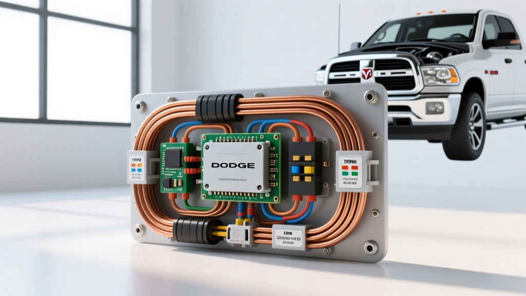
Sourcing the Right Dodge Ram 1500 Wiring Diagram Free PDF
When planning a high-current electrical modification for a 4th-generation (2013-2018) or 5th-generation (2019-present) truck, accessing accurate schematics is non-negotiable. When searching for a Dodge Ram 1500 wiring diagram free PDF, many DIYers end up with outdated, low-resolution, or generic schematics that omit critical CAN-bus routing and Totally Integrated Power Module (TIPM) pinouts. For upgrade and modification projects—such as installing a 12,000 lb winch solenoid pack, a 6-relay auxiliary light bar harness, or a dual-battery isolator—you need factory-level precision.
The most reliable resource for these schematics is the Mopar Connection Repair Site. While a full subscription is required for the interactive wiTECH diagrams, many independent automotive electrical forums and Haynes manuals provide extracted PDF versions of the Power Distribution Center (PDC) and Body Control Module (BCM) pinouts. Relying on verified Haynes Automotive Repair Manuals ensures you are looking at the correct chassis-specific harness routing, which varies significantly between the Quad Cab and Crew Cab configurations due to wheelbase length and rear chassis grounding points.
The Danger of Direct TIPM Taps in Modification Projects
The 2011-2018 Dodge Ram 1500 utilizes a TIPM (Totally Integrated Power Module) located in the under-hood engine bay. The TIPM replaces traditional fuse blocks with a multi-layer printed circuit board (PCB) containing internal micro-relays and surface-mount fuses. A common and catastrophic mistake during lighting or winch upgrades is tapping directly into the TIPM's high-current output traces to feed aftermarket accessories.
Drawing an additional 30A to 40A for an LED light bar or winch contactor through a circuit not designed for that continuous load will overheat the internal PCB traces, leading to melted solder joints and a complete TIPM failure. A replacement TIPM can exceed $1,200 and requires dealer-level programming to match the truck's VIN and axle ratio. The correct engineering practice is to use the TIPM or BCM only for low-current relay triggers (drawing less than 2A), while routing the primary high-current load directly from the battery or the dedicated auxiliary PDC studs.
Designing the Auxiliary Relay Harness
For a professional-grade auxiliary lighting upgrade, you must build or purchase a heavy-duty relay harness utilizing Bosch-style 5-pin ISO mini relays. These relays isolate the high-current load from the factory switchgear.
AWG Sizing and Current Draw Calculations
Automotive wire sizing must adhere to SAE J1128 Primary Cable Standards, which account for the high ambient temperatures under the hood of a Ram 1500 (often exceeding 125°C near the exhaust manifolds). Never use Copper Clad Aluminum (CCA) wire for high-current DC applications; it is brittle and prone to voltage drop. Always specify Oxygen-Free Copper (OFC) or tinned marine-grade copper.
| Wire Gauge (AWG) | Max Amperage (Engine Bay) | Max Amperage (Cabin) | Common Modification Application |
|---|---|---|---|
| 18 AWG | 6A | 10A | Relay coil trigger, BCM signal tap |
| 14 AWG | 15A | 20A | Low-draw LED pod lights, interior switch illumination |
| 10 AWG | 30A | 40A | Main feed to 40A ISO relay (Light bars, compressors) |
| 4 AWG | 120A | 150A | Dual battery isolator, heavy-duty inverter feed |
| 2/0 AWG | 200A+ | 200A+ | Winch solenoid pack, starter motor bypass |
Integrating Factory Upfitter Switches (2013-2018 Ram 1500)
If your Ram 1500 is equipped with the factory Upfitter Switch package (four auxiliary buttons located on the overhead console or lower dash), you have a massive advantage for modification projects. These switches do not carry the load current; instead, they send a signal to the BCM, which then grounds the coil side of four dedicated auxiliary relays located in the under-hood PDC.
To trigger your aftermarket lighting relays, you will tap into the load side output pigtails provided by Ram. These are typically found bundled in a corrugated loom near the driver's side firewall, taped up and capped from the factory.
Upfitter Relay and Pinout Specifications
| Switch / Relay | Amperage Rating | Wire Color (Output Pigtail) | Recommended Use |
|---|---|---|---|
| Aux 1 | 30A | Violet with White Tracer | Main 50-inch LED Light Bar (via 40A external relay) |
| Aux 2 | 30A | Violet with Brown Tracer | On-Board Air Compressor / Winch In-Dash Trigger |
| Aux 3 | 15A | Violet with Grey Tracer | Amber Ditch Lights / Scene Lights |
| Aux 4 | 15A | Violet with Yellow Tracer | Relay trigger for under-hood work lights |
Pro-Tip: When splicing into the Violet upfitter wires, use an adhesive-lined butt connector or a high-quality solder seal splice. Standard crimp caps will allow moisture ingress, leading to copper oxidation (green rot) and intermittent relay triggering within six months.
High-Current Winch Solenoid Routing and Grounding
Mounting a winch solenoid pack in the engine bay of a Ram 1500 requires careful routing to avoid the exhaust manifolds and the steering shaft U-joints. The primary power and ground cables feeding the solenoid must be 2/0 AWG welding cable. Standard battery cable is often too stiff to route cleanly through the Ram's tight inner fender wells.
Grounding is where 90% of high-current modification projects fail. Do not ground your winch solenoid or heavy-duty relay block to a painted frame rail or a thin sheet metal bracket. Locate the factory M10 chassis ground stud on the driver's side frame rail near the front tow hook. Remove the factory nut, use a wire wheel to strip the chassis down to bare, shiny steel, and attach your aftermarket 2/0 AWG ground lug. Torque the M10 nut to 35 ft-lbs (47 Nm) and coat the entire connection in No-Ox-Id A-Special conductive grease to prevent galvanic corrosion between the copper lug and the steel frame.
Crimping and Termination Standards
For any wire 8 AWG or larger, mechanical crimping with standard pliers is unacceptable. You must use a hydraulic crimper with the correct hex-die size to ensure a gas-tight connection between the copper strands and the terminal lug. After crimping, seal the terminal with dual-wall, adhesive-lined heat shrink. The inner wall melts and flows into the wire strands, creating a waterproof seal that prevents capillary action from drawing moisture under the insulation jacket.
Troubleshooting Modification Failure Modes
Even with a perfect Dodge Ram 1500 wiring diagram free PDF, physical installation errors can cause system failures. Use this decision tree to diagnose common upgrade issues:
- Symptom: Auxiliary lights flicker when the engine is idling, but stabilize at higher RPMs.
- Cause: Severe voltage drop on the ground side, or the alternator cannot keep up with the idle draw.
- Fix: Check the chassis ground with a multimeter under load. Voltage drop across a ground connection should not exceed 0.1V. If it does, clean the ground stud or upgrade to a 4 AWG ground wire.
- Symptom: The aftermarket relay clicks rapidly (chatters) when the upfitter switch is engaged.
- Cause: High resistance in the trigger circuit, often caused by a poor splice on the factory Violet/White upfitter wire, or a failing ISO relay coil.
- Fix: Measure the voltage at the relay's Pin 86 (trigger) while the switch is active. If it reads below 11.5V, cut out the splice and re-terminate using a solder-seal connector.
- Symptom: Winch solenoid engages, but the motor turns slowly and the battery terminals get extremely hot.
- Cause: Undersized wiring (using 4 AWG instead of 2/0 AWG) or loose battery terminal adapters.
- Fix: Verify battery terminal nut torque (typically 45 in-lbs for side-post adapters on the Ram's H7 or Group 94R battery). Upgrade the primary feed to 2/0 AWG OFC cable.
By respecting the factory electrical architecture, utilizing the correct AWG sizing, and properly leveraging the Ram's upfitter circuits, your modification project will be both reliable and safe for years of off-road use.