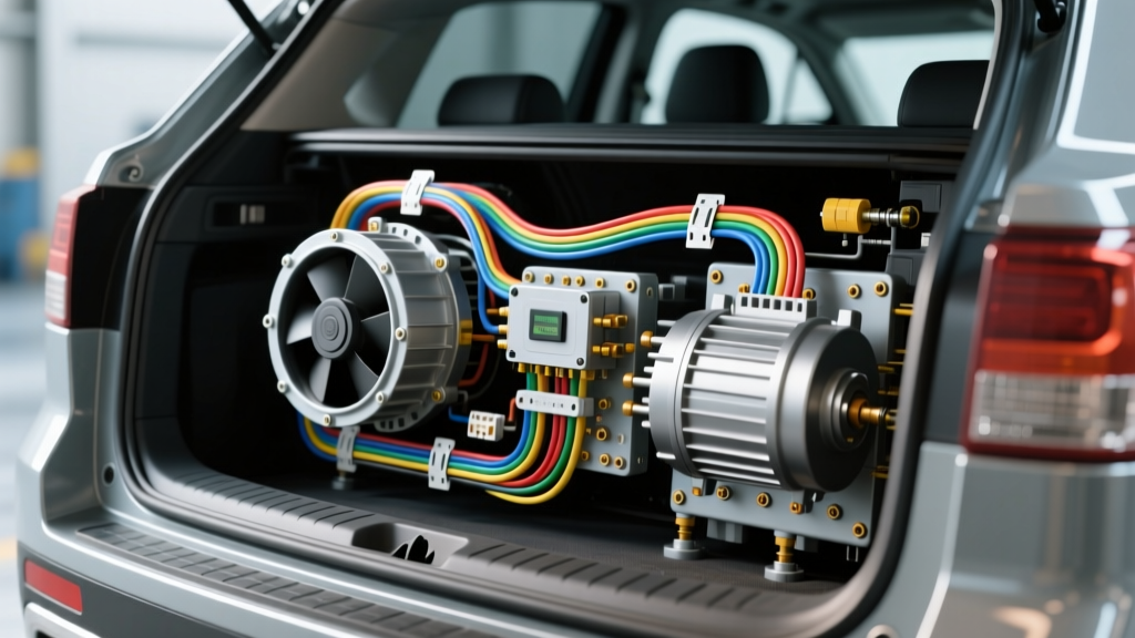
Automotive Air Handler Architecture: Understanding the Rear HVAC Circuit
While residential technicians use the term 'air handler' for indoor furnace units, in the automotive electrical sector—specifically regarding full-size SUVs and vans like the Chevy Tahoe, GMC Yukon, and Ford Expedition—the 'air handler' refers to the Rear HVAC Blower Motor Assembly and its integrated Control Processor. When rear climate control fails, automotive electricians must consult the specific wiring diagram for air handler circuits to isolate whether the fault lies in the dash-mounted control head, the pulse-width modulation (PWM) signal wire, or the high-amperage blower motor itself.
The rear air handler circuit in modern GMT900 and K2XX platform vehicles operates on a switched-power and PWM-ground architecture. Unlike older resistor-block systems that waste energy as heat, the modern air handler processor uses high-frequency switching to control motor speed efficiently. However, this complexity introduces specific failure modes, such as melted Metri-Pack connectors and failed semiconductor switches inside the processor module.
System Specifications and Wire Color Codes
Before beginning the step-by-step diagnostic flow, familiarize yourself with the standard Delphi Metri-Pack 280 series connector pinout commonly found at the rear air handler processor module:
- Pin A (Battery Feed): Red wire, 10 AWG. Constant 12V from the 30A HVAC fuse in the rear fuse block.
- Pin B (Chassis Ground): Black wire, 10 AWG. Dedicated ground point, usually located on the rear C-pillar or wheel well.
- Pin C (PWM Signal): Yellow or Yellow/Blue tracer, 18 AWG. Carries the duty-cycle signal from the Rear HVAC Control Module.
- Pin D (Motor Feed): Purple wire, 12 AWG. Output from the processor to the blower motor.
- Pin E (Motor Ground): Black/White wire, 12 AWG. Return path from the motor to the processor's internal switching transistor.
Step-by-Step Troubleshooting Flow
Follow this sequential diagnostic tree to accurately diagnose rear air handler failures without throwing unnecessary parts at the vehicle. According to Haynes Electrical Diagnostic Guidelines, always verify the power and ground foundation before testing low-voltage signal circuits.
Step 1: Visual Inspection and Connector Terminal Tension
The most common failure point in the air handler circuit is not the electronic module itself, but the physical connector. The rear blower motor can draw upwards of 15 to 18 amps on startup. If the terminal tension inside the 6-pin connector has degraded, electrical resistance increases. This resistance generates immense heat, melting the plastic housing and deforming the female terminals.
- Disconnect the negative battery terminal to prevent shorting the 10 AWG constant 12V feed.
- Unplug the harness connector at the rear air handler processor.
- Inspect Pins A and B for signs of thermal distortion, brown scorch marks, or melted plastic.
- Perform a 'drag test' using a spare male terminal. If the female terminal does not grip the test pin firmly, the entire pigtail must be spliced and replaced using solder-seal heat shrink connectors. Never use crimp-only butt connectors for 10 AWG high-amperage HVAC circuits.
Step 2: Voltage Drop Testing the 10 AWG Feed and Ground
If the connector is physically sound, the next step is verifying that the heavy-gauge wires can deliver adequate current under load. A standard 12V test light is insufficient here; you must use a digital multimeter (DMM) to perform a dynamic voltage drop test.
- Reconnect the battery and turn the rear HVAC system to maximum speed.
- Set your DMM to DC Volts. Place the positive probe on the battery positive post and the negative probe on Pin A (Red 10 AWG wire) at the back of the connector. A reading above 0.2V indicates excessive resistance in the fuse block or wiring harness.
- Place the positive probe on Pin B (Black 10 AWG wire) and the negative probe on the battery negative post. A reading above 0.1V indicates a corroded chassis ground point. Clean the ground ring terminal and underlying sheet metal with a wire brush, and apply dielectric grease upon reassembly.
Step 3: Validating the PWM Signal from the Control Head
If power and ground are confirmed, the air handler processor relies on a Pulse Width Modulation (PWM) signal to dictate blower speed. The Rear HVAC Control Module sends a 12V square wave signal, varying the duty cycle from roughly 10% (low speed) to 90% (high speed). Standard multimeters often misread PWM signals as fluctuating DC voltage. To properly test this, reference the SAE International standards for automotive electrical signal testing and use an oscilloscope or a DMM with a dedicated Duty Cycle setting.
- Back-probe Pin C (Yellow 18 AWG) with a T-pin or specialized back-probe tool.
- Connect your oscilloscope or DMM. Turn the rear blower speed from 1 to 7.
- Observe the duty cycle. It should step up linearly (e.g., 15%, 25%, 40%, 55%, 70%, 85%, 95%).
- Diagnostic Branch: If the signal remains flat at 0V or 12V regardless of switch position, the fault lies upstream in the dash-mounted Rear HVAC Control Head or a broken 18 AWG wire. If the signal varies correctly but the blower does not spin, the air handler processor is internally failed.
Step 4: Blower Motor Amp Draw and Binding Test
A frequently overlooked cause of repeated air handler processor failure is a binding blower motor. If the motor's bushings are dry or the squirrel cage is packed with debris, the motor will draw excessive amperage. This over-amp condition will fry the internal MOSFETs of a brand-new processor within weeks of installation.
- Disconnect the motor from the processor (Pins D and E).
- Use a fused jumper wire to apply direct 12V battery power and ground to the blower motor terminals.
- Clamp an inductive DC Amp Clamp around the positive jumper wire.
- A healthy rear blower motor should draw between 8A and 12A at free-spin. If the draw exceeds 16A, or if you hear mechanical grinding, the motor assembly must be replaced alongside the processor to prevent warranty-return failures.
Symptom-to-Cause Diagnostic Matrix
Use this quick-reference table to map customer complaints to specific wiring diagram nodes and diagnostic actions.
| Customer Symptom | Suspect Circuit Node | Diagnostic Action | Expected Result / Fix |
|---|---|---|---|
| Rear blower stuck on High only | Pin C (PWM Signal) or Processor Internal Short | Check for 12V short-to-power on Yellow 18 AWG wire. | If wire is shorted, repair harness. If wire is clear, replace air handler processor. |
| Rear blower completely dead | Pin A (12V Feed) or Pin B (Ground) | Perform voltage drop test on 10 AWG Red and Black wires. | Check rear fuse block 30A HVAC fuse and C-pillar ground ring terminal. |
| Blower works intermittently over bumps | Connector Terminal Tension / Motor Brushes | Perform terminal drag test; tap motor housing while powered. | Replace pigtail connector or blower motor assembly if brushes are worn. |
| Processor melts repeatedly | Pins D & E (Motor Circuit) | Measure blower motor amp draw under direct 12V load. | Replace binding blower motor if amp draw exceeds 16A. |
Expert Insights: Splicing and Environmental Protection
When repairing the 10 AWG power feed or ground wires at the air handler connector, environmental sealing is critical. The rear HVAC assembly is often located in the rear quarter panel or under the rear cargo area, zones highly susceptible to moisture intrusion from tailgate seals and rear wheel well splash guards.
According to Delphi Technologies connector specifications, any splice made in the Metri-Pack 280 harness must utilize adhesive-lined, dual-wall heat shrink tubing. The inner meltable adhesive layer creates a waterproof seal that prevents capillary action from wicking moisture up the copper strands and into the processor module. Standard vinyl electrical tape will fail in this environment due to the extreme thermal cycling generated by the high-amperage blower circuit.
By strictly following this wiring diagram for air handler troubleshooting flow, you eliminate guesswork, prevent repeat failures, and ensure the rear cabin climate control operates at factory specifications. Always verify the foundation of power and ground before condemning the solid-state control modules.