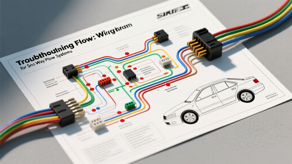
Introduction to Sno-Way Multiplex Electrical Systems
Sno-Way snow plows, particularly the MVP (Multi-Vantage Plow) and Pro series, utilize a sophisticated multiplex electrical architecture. Unlike older relay-based systems that require heavy-gauge wires for every function, Sno-Way's multiplex system sends digital signals over a lightweight data bus to a receiver module mounted on the plow. This receiver module then actuates high-current solenoids and the hydraulic motor. Because of this architecture, having the correct wiring diagram for Sno Way plow applications is critical; testing a multiplex data line with a standard incandescent test light can permanently damage the Command Module. This step-by-step troubleshooting flow is designed for automotive electrical technicians and advanced DIYers to systematically isolate faults from the cab controller to the hydraulic pump assembly.
Essential Tools and Safety Protocols
Before beginning any diagnostic procedure, ensure the vehicle's ignition is off and the plow is safely supported on jack stands if working underneath the blade assembly. You will need the following specialized tools:
- Digital Multimeter (DMM): A high-impedance DMM (minimum 10 Megohm input impedance) like the Fluke 87V is mandatory to avoid loading down multiplex circuits.
- Logic Probe or LED Test Light: Never use incandescent test lights on Sno-Way data lines. Use a high-impedance logic probe to verify PWM (Pulse Width Modulation) signals.
- Wire Piercers vs. Back-Probing: Avoid piercing the insulation of the control harness, as moisture intrusion will cause rapid galvanic corrosion. Always back-probe connectors using specialized terminal probes.
- Breakout Box: If available, a Sno-Way specific diagnostic breakout box allows you to monitor live data pins without risking terminal spread.
Step 1: Verify Main Power and Ground Integrity
The most common cause of erratic plow behavior is not a failed control module, but excessive voltage drop on the primary power circuits. The wiring diagram for Sno Way plow systems dictates strict AWG requirements for the main battery feed and ground.
Testing the Main Motor Feed (4 AWG / 2 AWG)
- Locate the main battery isolation solenoid under the hood. Verify that the heavy-gauge battery cable (typically 4 AWG for standard runs, 2 AWG for extended wheelbase trucks) has a clean, torqued connection at the battery positive terminal (torque to 12-15 lb-ft depending on terminal type).
- Set your DMM to DC Volts. Place the red probe on the battery positive post and the black probe on the plow motor's main power stud.
- Engage the plow raise function. A voltage drop reading greater than 0.50V indicates excessive resistance in the power cable or the isolation solenoid contacts.
Testing the Main Ground (2 AWG)
- The Sno-Way motor ground must return directly to the vehicle's battery negative terminal or a verified clean engine block ground tied directly to the battery.
- Place the red DMM probe on the motor casing (bare metal) and the black probe on the battery negative post.
- Activate the motor. A voltage drop exceeding 0.20V on the ground side requires immediate cleaning or replacement of the 2 AWG ground cable and ring terminals.
Step 2: Diagnosing the Multiplex Control Harness
The control harness bridges the in-cab Command Module to the plow-mounted Receiver Module. According to SAE J1128 Low Tension Primary Cable Standards, these wires are typically 16 AWG or 18 AWG cross-linked polyethylene (XLPE) designed to withstand severe under-hood temperatures.
Verifying the Ignition and Data Lines
The 13-pin or 7-pin connector (depending on your specific Sno-Way generation) carries both power and data.
- Ignition Feed: Back-probe the red wire (Pin 1 on most 13-pin layouts) with the key in the 'RUN' position. You should read within 0.2V of battery voltage. If voltage is low, trace the circuit back to the vehicle's upfitter switch or ignition-run fuse block.
- Data Bus Communication: Connect a digital storage oscilloscope (DSO) or a specialized multiplex logic probe to the data lines (often Green and White wires). You are looking for a clean 12V square wave or PWM signal when a button is pressed on the cab controller. A flattened or noisy waveform indicates a short to ground, a short to power, or a failing termination resistor inside the Command Module.
Step 3: Solenoid and Motor Circuit Testing
Sno-Way hydraulic systems utilize 12V DC cartridge-style solenoid valves. If the cab controller registers a button press but the hydraulic cylinder does not move, the fault lies between the Receiver Module output and the solenoid coil.
- Disconnect the solenoid connector at the valve bank.
- Measure the coil resistance across the two solenoid terminals. A healthy Sno-Way hydraulic solenoid should read between 6.0 and 12.0 ohms at room temperature. A reading of OL (Open Loop) means an internal coil break; a reading near 0.0 ohms indicates a shorted coil that may have damaged the Receiver Module's internal MOSFET driver.
- Check the wiring harness between the Receiver Module and the valve bank for chafing, especially near the pivot points where the harness flexes during angling operations.
Sno-Way 13-Pin Connector Pinout and Wire Color Reference
When consulting the wiring diagram for Sno Way plow setups, the 13-pin weather-pack connector is the primary diagnostic junction. Below is the standard pinout configuration for modern MVP systems. Always verify against the specific OEM schematic for your exact model year.
| Pin | Wire Color | AWG | Function / Circuit Description |
|---|---|---|---|
| 1 | Red | 10 | Switched 12V+ Ignition Feed (Cab to Plow) |
| 2 | Black | 10 | Main System Ground (Cab to Plow) |
| 3 | Blue | 16 | Multiplex Data Line A (Raise/Lower Command) |
| 4 | Green | 16 | Multiplex Data Line B (Left Angle Command) |
| 5 | White | 16 | Multiplex Data Line C (Right Angle Command) |
| 6 | Brown | 16 | Down Pressure PWM Signal (MVP Systems) |
| 7 | Yellow | 18 | System Status / Diagnostic Feedback to Cab |
| 8 | Orange | 18 | Lighting Circuit: Left Turn / Brake |
| 9 | Purple | 18 | Lighting Circuit: Right Turn / Brake |
| 10 | Gray | 18 | Lighting Circuit: Running / Marker Lights |
| 11 | Light Blue | 18 | Lighting Circuit: High Beam Headlights |
| 12 | Dark Green | 18 | Lighting Circuit: Low Beam Headlights |
| 13 | Red/White | 14 | Constant 12V+ Battery Memory Feed |
Common Failure Modes and Symptom Decision Tree
Use this diagnostic decision tree to quickly isolate the root cause of common Sno-Way electrical faults. For deeper integration issues with specific truck OEM upfitter modules, refer to the Sno-Way Official Technical Support Portal for vehicle-specific integration bulletins.
Symptom 1: Plow Motor Runs Continuously After Releasing 'Raise' Button
- Cause A: Stuck Motor Solenoid. The high-current contacts inside the main motor solenoid have welded together due to arcing.
- Test: Disconnect the small trigger wire (usually white or yellow, 16 AWG) from the solenoid coil. If the motor continues to run, the solenoid is mechanically welded.
- Fix: Replace the main motor solenoid. Inspect the motor brushes, as a failing motor drawing excessive amps is the primary cause of solenoid welding.
- Cause B: Shorted Receiver Module Output. Internal MOSFET failure.
- Test: If the trigger wire shows 12V+ even when the cab controller is off, the Receiver Module is shorted internally.
- Fix: Replace the Receiver Module and verify the motor amperage draw is within spec (typically under 150A under load).
Symptom 2: Cab Controller Displays 'No Communication' or Flashing LED
- Cause A: Blown Ignition Fuse or Bad Ground at Cab Module.
- Test: Verify 12V+ at Pin 1 and continuity to ground at Pin 2 on the cab side of the harness.
- Fix: Repair the 10 AWG ignition feed or clean the cab ground ring terminal.
- Cause B: Broken Data Wire in the Flex Loom.
- Test: Perform a continuity test on Pins 3, 4, and 5 from the cab connector to the plow connector while wiggling the harness near the vehicle's front bumper.
- Fix: Splice and seal the broken 16 AWG wire using adhesive-lined heat shrink. Do not use standard electrical tape, as it will unravel and allow moisture ingress.
Symptom 3: Plow Angles Left but Will Not Angle Right
- Cause A: Failed Right Angle Solenoid Coil.
- Test: Measure resistance across the right angle solenoid terminals. Expect 6-12 ohms.
- Fix: Replace the cartridge solenoid. Ensure the O-ring is properly lubricated with hydraulic fluid during installation to prevent pinching.
- Cause B: Open Circuit in Harness (Pin 5 White Wire).
- Test: Check for 12V PWM signal at the Receiver Module output for the right angle function when the joystick is commanded right.
- Fix: Repair the open wire or replace the control harness if multiple conductors show signs of chafing.
Conclusion and Best Practices
Troubleshooting a Sno-Way multiplex system requires a methodical approach and a strict adherence to the wiring diagram for Sno Way plow configurations. By verifying heavy-gauge power and ground circuits first, you eliminate 80% of perceived 'module' failures. Always protect the integrity of the 16 AWG and 18 AWG multiplex data lines by back-probing rather than piercing, and ensure all exterior connections are sealed with dielectric grease to prevent the galvanic corrosion that plagues winter equipment. When replacing components, always use OEM-specified solenoids and modules to maintain the precise PWM duty cycles required for features like Down Pressure and variable speed angling.