Introduction to RV Electrical Architecture
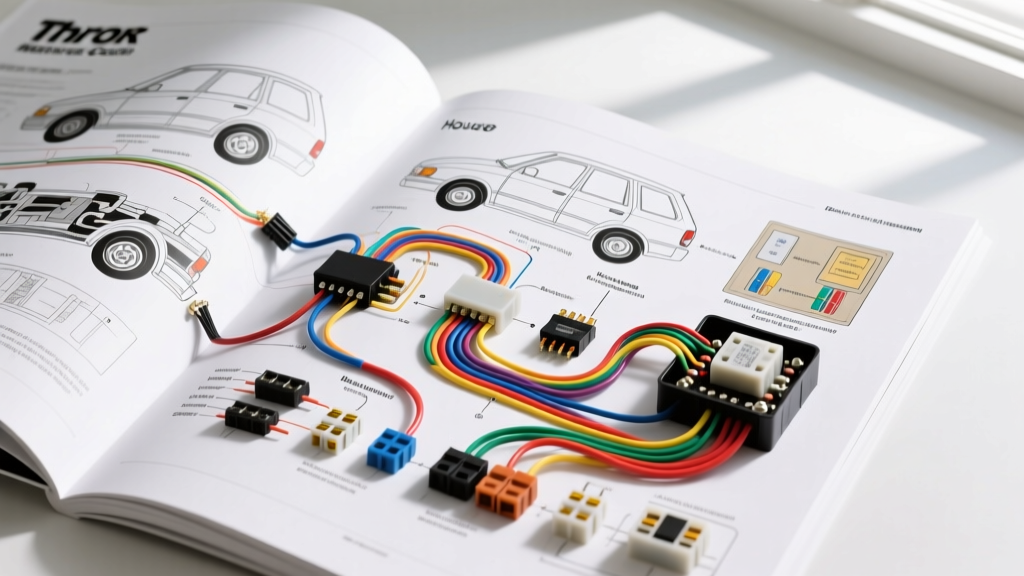
When you first open a Thor Motor Coach wiring diagram PDF, the sheer volume of lines, symbols, and circuit paths can be overwhelming for a beginner. Unlike standard passenger vehicles, Class A and Class C motorhomes operate on a complex dual-electrical architecture. To successfully troubleshoot or upgrade your RV, you must first understand that your motorhome is essentially two separate vehicles wired into one living space.
The first system is the Chassis Electrical System, which is designed and manufactured by the OEM (typically Ford for the E-Series/Triton V10 or Chevrolet for the Express 6.0L). This system handles the engine ECU, headlights, alternator, and starter. The second is the House (Coach) Electrical System, built by Thor Motor Coach. This system manages your 12V DC interior lighting, water pump, slide-out motors, and the 120V AC shore power and inverter circuits.
A complete Thor Motor Coach wiring diagram PDF will usually separate these two systems into distinct sections. Understanding how to navigate this document is the first step toward mastering RV electrical diagnostics.
Navigating Your Thor Motor Coach Wiring Diagram PDF
Thor provides build-specific schematics based on your model, floorplan, and production date. When reading the coach section of the PDF, keep these fundamental schematic rules in mind:
- Power Flow: Power sources (batteries, converters, shore power) are almost always located at the top of the diagram. Ground points (chassis ground or DC negative bus bars) are located at the bottom.
- Relays and Solenoids: Look for rectangular boxes with diagonal lines or coil symbols. In Thor diagrams, a continuous-duty solenoid (like the BIRD system) will show heavy-gauge input/output terminals alongside smaller signal terminals.
- Switches: Single-pole single-throw (SPST) switches are drawn as simple open gaps in the wire line. Momentary switches (used for slide-outs and awnings) will feature a spring-return symbol.
- Connectors: Multi-pin connectors are represented by dashed boxes with pin numbers inside. Thor frequently uses Molex connectors for interior low-current harnesses and Deutsch DT series connectors for exterior, weather-exposed components.
Standard Thor House Wire Color and AWG Chart
One of the most valuable aspects of the wiring diagram PDF is the color code legend. While chassis wiring follows Ford or GM standards (e.g., Ford uses Light Green/Purple for the fuel pump), Thor's house wiring adheres to RV Industry Association (RVIA) guidelines. Below is a reference chart for standard Thor house wiring colors and American Wire Gauge (AWG) sizes.
| Circuit Type | Standard Wire Color | Typical AWG Size | Common Application |
|---|---|---|---|
| 12V DC Positive | Red | 14 AWG to 10 AWG | Interior lighting, water pump, 12V receptacles |
| 12V DC Negative | White | 14 AWG to 10 AWG | DC ground return to bus bar |
| 120V AC Hot | Black | 12 AWG to 10 AWG | Shore power distribution, AC outlets |
| 120V AC Neutral | White | 12 AWG to 10 AWG | AC return path |
| 120V AC Ground | Green (or Bare) | 12 AWG to 10 AWG | Chassis bonding, AC safety ground |
| Slide-Out Motor | Blue / Yellow | 6 AWG | High-draw DC slide room actuators |
| Inverter DC Feed | Red / Black | 2/0 AWG | Main battery bank to inverter/charger |
Note: Always verify against your specific Thor Motor Coach wiring diagram PDF, as custom floorplans or aftermarket dealer modifications may deviate from standard color codes.
Understanding the BIRD Solenoid System
Beginners often get confused by the Battery Isolator Relay Delay (BIRD) system found in the PDF schematics. The BIRD system allows your house batteries to charge while driving (via the chassis alternator) and your chassis battery to charge while plugged into shore power (via the house converter).
In the diagram, locate the Trombetta continuous-duty solenoid. It acts as a heavy-duty bridge between the two battery banks. You will see four primary wires connected to it:
- Terminal A (Large): 12V+ from the Chassis Battery (typically 4 AWG or 2 AWG Red).
- Terminal B (Large): 12V+ from the House Battery Bank (typically 4 AWG or 2 AWG Red).
- Signal Terminal 1 (Small): 12V+ ignition signal or BIRD controller signal (14 AWG).
- Signal Terminal 2 (Small): Ground (14 AWG White).
If your house batteries are not charging while driving, the PDF will guide you to test the small signal wires first. If the BIRD controller isn't sending the 12V signal to the solenoid coil, the heavy contacts will never close, isolating the batteries.
Essential Tools for Beginner RV Troubleshooting
Before you attempt to trace a circuit using your Thor schematic, ensure you have the correct tools. Guessing with RV electricity can lead to melted harnesses or damaged control boards.
- Digital Multimeter (DMM): A basic DMM is mandatory for checking DC voltage, AC voltage, and continuity. Look for a meter with a low-impedance (LoZ) setting to avoid ghost voltage readings in long RV wire runs.
- Tone Generator and Probe: Invaluable for tracing a specific 12V DC wire through a bundled harness behind the dashboard or under the bed without stripping back insulation.
- Wire Tracer/Breaker Finder: Essential for identifying which 120V AC breaker in your main distribution panel controls a specific outlet or appliance.
Step-by-Step: Testing a 12V DC House Circuit
Let's apply the Thor Motor Coach wiring diagram PDF to a real-world scenario: your 12V overhead LED lights in the bedroom are not turning on. Here is how a beginner should approach the diagnostic process using the schematic.
Step 1: Verify Power at the Distribution Panel
Locate the 12V DC fuse block (usually integrated with the AC breaker panel). Find the fuse labeled "Bedroom Lights" (typically a 10A or 15A automotive blade fuse). Use your multimeter to check for 12.6V on both sides of the fuse. If power is missing at the fuse, the issue is upstream at the house battery disconnect solenoid or the main 12V DC bus bar.
Step 2: Test the Switch
Follow the diagram from the fuse to the wall switch. The PDF will show a Red (12V+) wire entering the switch and a switched leg (often Blue or Yellow) exiting toward the lights. Set your multimeter to DC Volts. Place the black probe on a known good ground (like a metal chassis bolt) and the red probe on the output side of the switch. Toggle the switch. If voltage reads 12.6V, the switch is good, and the problem is downstream.
Step 3: Check the Ground Connection
According to the RV Industry Association (RVIA) standards, 12V DC grounds must terminate at a dedicated ground bus bar, not simply screwed into the wood framing. If you have 12V+ at the light fixture but the LED won't illuminate, use your multimeter's continuity setting (with the power turned OFF) to test the White ground wire from the fixture back to the ground bus bar. High resistance indicates a corroded crimp or a loose bus bar screw.
Safety Warnings and Best Practices
When working with the 120V AC sections of your Thor Motor Coach wiring diagram PDF, always disconnect from shore power and turn OFF the main AC breaker before opening any junction boxes or outlet covers. RV AC systems lack the GFCI protection standard in modern homes, making shocks a severe hazard.
Furthermore, when replacing fuses or relays identified in your PDF, never exceed the specified amperage. Upgrading a 10A fuse to a 15A fuse to stop it from blowing will bypass the wire's thermal limits, potentially causing a fire inside the RV walls. For comprehensive OEM chassis data, refer to the Ford Motorhome Chassis Resources, and always keep a digital or printed copy of your specific build's diagrams from the Thor Motor Coach Owner Resources portal in your rig at all times.
Conclusion
Learning to read a Thor Motor Coach wiring diagram PDF is a foundational skill for any RV owner. By understanding the separation of chassis and house systems, memorizing standard RV wire colors, and methodically tracing circuits from power to ground, you can confidently diagnose and repair electrical faults. Take your time, rely on your multimeter, and let the schematic be your roadmap to a fully functional motorhome electrical system.