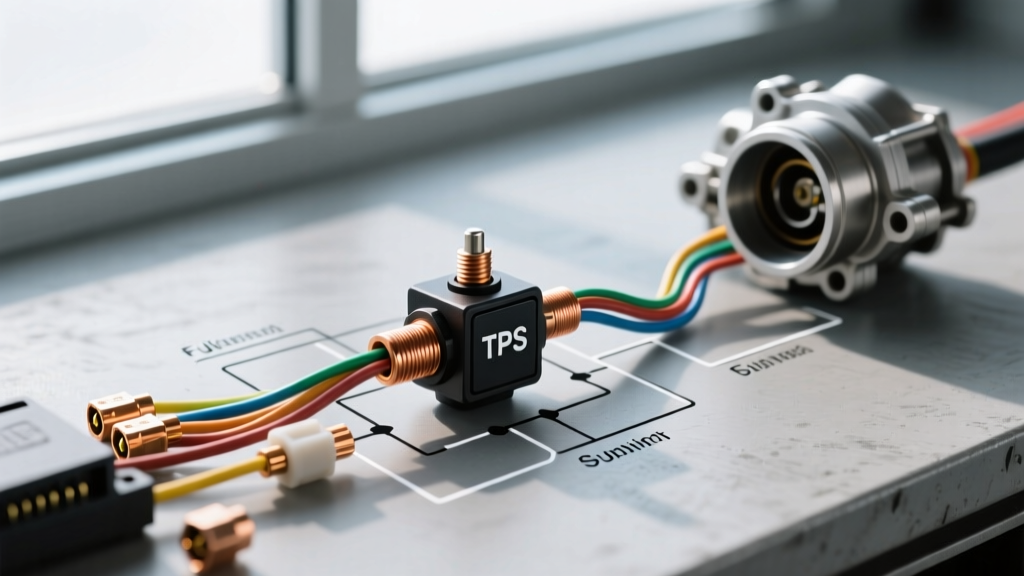
The Hidden Dangers in a Throttle Position Sensor Wiring Diagram
When diagnosing drivability issues, hesitation, or erratic shifting, technicians and DIYers frequently consult a throttle position sensor wiring diagram to trace the signal path. However, a schematic only provides a theoretical map of the circuit; it does not warn you about the physical and electrical hazards inherent in testing and repairing these sensitive wires. The Throttle Position Sensor (TPS) is a critical potentiometer that translates mechanical throttle blade angle into a variable voltage signal for the Engine Control Unit (ECU). Because this signal directly dictates fuel injection pulse width, ignition timing, and transmission shift points, any interference, voltage drop, or short circuit can lead to catastrophic engine damage or an un-drivable vehicle.
This guide explores the most severe mistakes made when interpreting and working with TPS wiring diagrams, focusing on safety warnings, improper probing techniques, and the rapid destruction of ECU internal voltage regulators. Whether you are working on a classic 3-pin cable-driven TPS or a modern 6-pin Drive-By-Wire (DBW) redundant sensor, understanding these pitfalls is mandatory for safe automotive electrical repair.
Understanding the TPS Circuit Architecture
Before probing any wires, you must understand the standard 3-pin TPS architecture found on most cable-driven throttle bodies (such as the GM LS 5.3L or Ford 4.6L V8). The throttle position sensor wiring diagram will typically show three distinct circuits:
- Pin A (5V Reference): A highly regulated 5-volt supply originating from the ECU's internal linear voltage regulator. (Typically Gray or Red wire, 20 AWG).
- Pin B (Signal Return): The variable voltage output (usually 0.5V at idle to 4.5V at WOT) sent back to the ECU's Analog-to-Digital (A/D) converter. (Typically Dark Blue or Light Green, 20 AWG).
- Pin C (Low Reference / Sensor Ground): A dedicated, clean ground path returning directly to the ECU, isolated from noisy chassis grounds. (Typically Black, 20 AWG).
Modern Drive-By-Wire (DBW) systems use a 6-pin connector housing two redundant potentiometers that sweep in opposite directions for safety verification. However, the foundational rules of testing the 5V reference and signal wires remain identical. Misinterpreting these pins on a wiring diagram is the leading cause of accidental ECU failure.
Fatal Mistake 1: Piercing the Signal Wire Insulation
One of the most common and destructive mistakes made when using a wiring diagram to locate the TPS signal wire is piercing the wire insulation with a T-pin, needle, or test probe to read the voltage. While this may yield an immediate voltage reading on your Digital Multimeter (DMM), it creates a guaranteed future failure.
Automotive wiring harnesses are subjected to extreme thermal cycling, moisture, and road salt. When you pierce the PVC or cross-linked polyethylene (XLPE) insulation, you expose the stranded copper core to the elements. Within weeks, capillary action will draw moisture under the insulation jacket, leading to copper oxide formation (green corrosion). This corrosion increases the resistance of the 20 AWG wire, causing a voltage drop that the ECU interprets as a failing TPS sensor. You will eventually replace a perfectly good sensor and still suffer from a P0121 (TPS Performance) code. Always use proper backprobing pins inserted into the rear of the connector cavity to make contact with the terminal without compromising the wire jacket.
Fatal Mistake 2: The 5V Reference Short (The ECU Killer)
A throttle position sensor wiring diagram clearly labels the 5V reference wire, but many technicians fail to realize how fragile the ECU's internal 5V voltage regulator is. A common safety warning ignored in the field is the use of incandescent test lights or low-impedance multimeters on the reference circuit.
If a technician accidentally shorts the 5V reference wire (Pin A) to a 12V battery positive source while probing, or uses a standard 12V test light that draws excessive current, the ECU's internal silicon junction will instantly overheat and fail. This often results in the ECU losing its ability to power not just the TPS, but the MAP sensor, camshaft position sensor, and fuel rail pressure sensor, as they often share the same 5V reference bus on the printed circuit board. Safety Rule: Never use a test light on any wire identified as a 5V reference on a schematic. Only use a high-impedance DMM (minimum 10 Megaohms input impedance) to prevent drawing current from the sensitive reference circuit.
Fatal Mistake 3: Confusing Sensor Ground with Chassis Ground
When a wiring diagram shows a ground symbol on Pin C, inexperienced diagnostic technicians often assume they can verify the ground by checking for continuity between the TPS connector and the engine block or chassis. This is a fundamental misunderstanding of automotive sensor circuits.
The TPS Low Reference wire is a dedicated signal ground that routes all the way back to a specific ground plane inside the ECU. It is designed to be free of the electrical noise generated by the alternator, ignition coils, and fuel injectors. If you attempt to 'fix' a perceived ground issue by splicing the TPS ground wire directly to the engine block, you will introduce alternating current (AC) noise and voltage offsets into the TPS signal return. The ECU will see erratic voltage sweeps, triggering false lean/rich fuel trims and erratic transmission shifting. Always verify the sensor ground by performing a voltage drop test between Pin C and the negative battery terminal with the key on; it should read less than 0.05V.
Safety & Consequence Matrix: TPS Wiring Errors
| Diagnostic Action | Risk Level | Consequence of Error | Correct Procedure |
|---|---|---|---|
| Piercing wire insulation with a needle | High (Delayed) | Moisture ingress, copper oxidation, intermittent P0122/P0123 codes. | Use dedicated backprobing pins at the connector cavity. |
| Testing 5V Ref with a 12V test light | Critical | Instant destruction of ECU internal 5V voltage regulator. | Use a high-impedance DMM (>10M Ohms) only. |
| Splicing TPS ground to engine block | Medium | Introduction of AC noise, erratic idle, false fuel trim codes. | Verify dedicated low-reference path back to ECU via voltage drop. |
| Soldering TPS harness repairs | High (Delayed) | Capillary wicking, brittle wire breakage inside connector boot. | Use OEM crimp terminals with marine-grade heat shrink seals. |
Fatal Mistake 4: Improper Harness Repair and Soldering
When a throttle position sensor wiring diagram leads you to a broken wire near the throttle body connector, the method of repair is just as critical as the diagnosis. Many DIYers and general mechanics default to twisting the wires together and applying solder, followed by electrical tape. According to Delphi Technologies Tech Resources, soldering automotive sensor wires is a severe violation of OEM repair standards.
Solder wicks into the stranded 20 AWG wire via capillary action, turning a flexible wire into a rigid, brittle rod. Because the TPS harness is subjected to constant engine vibration, the soldered joint will quickly fatigue and snap, often breaking inside the connector boot where it cannot be seen. Furthermore, electrical tape degrades under hood temperatures, unraveling and exposing the splice. The only acceptable repair method for a TPS signal or reference wire is to use a crimp-and-seal butt connector or, preferably, to replace the entire pigtail using OEM-specific crimp terminals and a proper ratcheting terminal crimper.
Real-World TPS Diagnostic Decision Tree
Use this structured decision tree when your scan tool data or DMM readings do not match the expected values on your wiring schematic:
- Symptom: TPS reads 0.0V at all throttle positions.
Test: Check Pin A for 5.0V. Check Pin C for <0.05V drop to battery negative.
Result: If 5V and Ground are present at the connector, the internal potentiometer wiper track is open. Fix: Replace TPS. - Symptom: TPS reads a steady 5.0V regardless of throttle movement.
Test: Disconnect TPS connector. Measure resistance between Pin B (harness side) and Pin C (harness side).
Result: If resistance is near 0 Ohms, the signal wire is shorted to the ground wire in the harness. Fix: Locate harness chafe point and repair. - Symptom: TPS voltage drops out intermittently during engine vibration.
Test: Connect DMM to Pin B using backprobes. Wiggle the harness 2 inches from the connector while monitoring.
Result: Voltage drops to 0V or spikes to 5V. Fix: Inspect connector cavity for terminal fretting, spread pins, or loss of terminal tension. Replace pigtail connector.
Conclusion and Industry Standards
A throttle position sensor wiring diagram is an essential diagnostic tool, but it must be paired with strict adherence to automotive electrical safety protocols. The ECU's 5V reference bus is highly sensitive, and the signal return wire demands absolute integrity to prevent drivability faults. By avoiding insulation piercing, respecting the 5V reference limits, maintaining isolated sensor grounds, and utilizing proper crimp-and-seal repair methods, you ensure the longevity of both the sensor and the engine management computer. For further reading on electromagnetic compatibility and wiring harness standards, refer to the SAE International Standards and the diagnostic tutorials provided by Haynes Technical Tutorials.