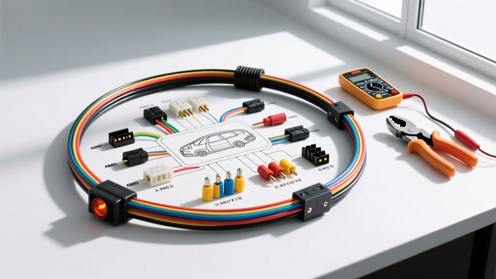
The True Cost of Turn Signal Circuit Diagnostics
When a turn signal fails, hyper-flashes, or stays on solid, the immediate instinct is to swap a bulb. However, modern vehicles utilize complex Body Control Modules (BCMs) and multiplexed circuits that require a deeper approach. Successfully interpreting a wiring diagram for turn signals is only the first step; the real challenge lies in having the correct diagnostic tools and materials to test, repair, and verify the circuit without causing secondary damage to sensitive automotive computers.
Dealerships typically charge a flat diagnostic fee ranging from $150 to $220 just to hook up a scan tool and print off the schematic. For the DIY technician or independent shop, understanding the tool requirements, material costs, and specific wire gauges associated with lighting circuits can turn a $300 dealership bill into a $20 bench repair. This guide breaks down the exact cost and tool requirements needed to professionally diagnose and repair turn signal circuits using OEM schematics.
Essential Diagnostic Tools & Investment Breakdown
You cannot accurately test a modern turn signal circuit with a simple incandescent test light. Modern BCMs monitor current draw on the lighting circuits to detect burnt-out bulbs (triggering the hyper-flash warning). An incandescent test light draws roughly 1.5 to 2 amps, which can trick the BCM into thinking a bulb is connected, or worse, blow the internal solid-state driver if a short exists. You must invest in high-impedance diagnostic tools.
| Tool Category | Recommended Model | Estimated Cost | Application in Turn Signal Diag |
|---|---|---|---|
| High-Impedance DMM | Innova 3320 or Fluke 87V | $25 - $250 | Checking for voltage drop, verifying ground integrity, and measuring BCM output voltage without loading the circuit. |
| LED Logic Probe | Lisle 56810 or Power Probe | $30 - $220 | Safe back-probing of multifunction switches and BCM pins. Draws milliamps, preventing BCM driver overload. |
| Terminal Back-Probes | Orion Motor Tech Pin Probe Set | $15 | Crucial for testing voltage at the BCM connector or bulb socket without piercing the wire insulation (which causes corrosion). |
| Terminal Removal Kit | Lisle 37500 Master Set | $35 | Extracting Metri-Pack or Weather-Pack terminals from the connector housing for replacement. |
The Hidden Cost of Piercing Wires
Many DIYers use 'T-taps' or pierce probes to test wires shown on the wiring diagram for turn signals. This is a critical error. Piercing the insulation of an 18 AWG wire exposes the copper strand to moisture, leading to galvanic corrosion and eventual wire breakage inside the loom. The $15 investment in proper back-probes saves you from having to replace entire wiring harnesses later.
Material Specifications: Wire, Terminals, and Relays
If your diagnosis reveals a chafed wire or a melted connector pigtail, you must replace it using automotive-grade materials. Standard household THHN wire or vinyl electrical tape will fail under the hood's thermal cycling. According to SAE J1128 Standards, automotive primary wire must withstand high temperatures and chemical exposure.
| Component | Specification | Cost (Per Unit/Foot) | Technical Notes |
|---|---|---|---|
| Wire (Main Feed) | 14 AWG GXL (Cross-Linked) | $0.45 / ft | Used from the battery/BCM to the flasher relay or main splice pack. Rated for 125°C. |
| Wire (Branch Runs) | 18 AWG TXL or GXL | $0.30 / ft | Standard for individual bulb runs. Handles up to 10A safely, well above the 2A draw of a standard 3157 bulb. |
| Terminals | Delphi Metri-Pack 150 | $0.15 / ea | Tin-plated brass. Requires a specific open-barrel crimp tool. See the Delphi Metri-Pack Catalog for pin dimensions. |
| Heat Shrink | Dual-Wall Adhesive (3M) | $1.20 / piece | Melts internally to create a watertight seal over splices. Mandatory for exterior lamp pigtails. |
Decoding the Wiring Diagram for Turn Signals (GM GMT900 Example)
To understand how your tools and materials apply, let us analyze a specific wiring diagram for turn signals from a popular platform: the GM GMT900 (Silverado/Sierra 1500). Unlike older vehicles that used a thermal flasher can on the fuse block, this vehicle uses a solid-state BCM to control the flash rate.
Multifunction Switch to BCM Logic
When you move the turn signal stalk, you are not directly sending 12V to the bulbs. Instead, the multifunction switch sends a low-current logic signal to the BCM.
- Left Turn Request: Yellow wire, BCM Connector X4, Pin 12.
- Right Turn Request: Dark Green wire, BCM Connector X4, Pin 13.
- Ground Reference: Black/White wire, BCM Connector X4, Pin 16.
Using your LED logic probe, you can back-probe Pin 12. When the stalk is moved left, the probe should illuminate, confirming the switch is sending the request. If the probe does not light up, the issue is in the steering column wiring or the switch itself, saving you from tearing apart the rear taillight harness.
BCM Output to the Lamps
Once the BCM receives the request and verifies the ignition is in the correct state, it pulses the high-current outputs to the exterior lamps.
- Left Front Output: Light Blue wire, BCM Connector X1, Pin 45.
- Right Front Output: Dark Blue wire, BCM Connector X1, Pin 46.
If the left front turn signal is inoperative, but the left rear is flashing rapidly (hyper-flash), the BCM has detected a lack of current draw on the front circuit. You must use your Digital Multimeter (DMM) to perform a voltage drop test on the Light Blue wire between BCM X1 Pin 45 and the front lamp socket. A voltage drop greater than 0.5V indicates high resistance, likely due to a corroded Metri-Pack terminal or a failing ground at the lamp socket.
Step-by-Step Diagnostic Workflow
Follow this systematic approach to minimize diagnostic time and avoid unnecessary part replacement. For a deeper understanding of foundational electrical testing, refer to Haynes Automotive Electrical Basics.
- Visual & Bulb Verification: Remove the bulb. Check the filament and the socket for corrosion. Note that many modern vehicles use 7443 CK sockets, where the ground pins are offset. Inserting a standard 7443 bulb into a CK socket will blow the BCM fuse.
- Ground Integrity Test: Set your DMM to Ohms. Measure resistance between the bulb socket ground terminal and the vehicle chassis bare metal. It should read less than 0.5 ohms. If higher, clean the chassis ground point and apply dielectric grease.
- Logic Signal Verification: Back-probe the BCM request pins (e.g., X4 Pin 12) with an LED test light to confirm the multifunction switch is operating.
- Output Voltage Test: With the hazard lights on, use the DMM to check for pulsing 12V at the BCM output pin (e.g., X1 Pin 45). If 12V is present at the BCM but not at the bulb, you have an open circuit in the wiring harness.
- Terminal Inspection: Use your terminal removal tool to extract the suspect pin from the connector housing. Inspect the open-barrel crimp for wire pull-out or oxidation.
Professional vs. DIY Cost Analysis
Let us compare the financial reality of a typical 'no-left-turn-signal' diagnosis where the root cause is a corroded Metri-Pack 150 terminal at the under-hood fuse block.
| Service Aspect | Dealership Route | DIY Route (With Proper Tools) |
|---|---|---|
| Initial Diagnosis | $180.00 (Flat Rate Diag) | $0.00 (Using owned DMM & Logic Probe) |
| Parts Replacement | $350.00 (Entire Engine Harness) | $12.00 (OEM Pigtail, 18 AWG GXL, Heat Shrink) |
| Labor | $450.00 (3 Hours @ $150/hr) | $0.00 (1 Hour DIY Time) |
| Total Cost | $980.00 | $12.00 |
Return on Investment (ROI)
The initial investment for a quality DMM ($50), an LED logic probe ($30), a terminal removal kit ($35), and a proper Delphi crimping tool ($85) totals roughly $200. As demonstrated in the table above, a single successful DIY repair using the correct wiring diagram for turn signals and precise diagnostic steps pays for the entire tool set immediately. Furthermore, you preserve the integrity of the vehicle's electrical system by utilizing adhesive-lined heat shrink and proper open-barrel crimps, ensuring the repair outlasts the vehicle itself.