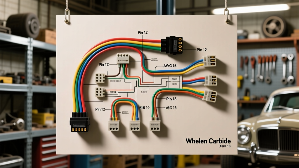
Introduction to Whelen Carbide Upfit Architecture
The Whelen Carbide series represents a benchmark in surface-mount and LED warning light technology for emergency vehicles, snowplows, and heavy-duty commercial trucks. Unlike legacy halogen or strobe systems that require massive current draws and high-voltage capacitor banks, the Carbide LED modules operate on highly efficient, solid-state microprocessors. However, this efficiency demands precise voltage regulation and meticulous wiring practices. A flawed Whelen Carbide wiring diagram implementation can lead to erratic flash patterns, synchronization drift, or catastrophic module failure due to voltage spikes.
This complete wiring walkthrough dissects the primary power distribution, control circuit pinouts, and synchronization (Sync) network topology required for a compliant, SAE-rated installation. Whether you are integrating a single Carbide surface-mount light or a full-vehicle perimeter warning system via a CENCOM controller, understanding the exact AWG requirements, connector specifications, and wire color codes is non-negotiable for professional upfitters.
Primary Power Distribution and Grounding Topology
The foundation of any emergency lighting schematic is a robust power distribution network. Whelen Engineering specifies that all primary power circuits for LED warning devices must be sourced directly from the vehicle battery or a dedicated, fused auxiliary power bus. Tapping into existing OEM chassis lighting circuits (such as the headlight or clearance light feeds) is strictly prohibited, as the pulse-width modulation (PWM) from modern vehicle body control modules (BCMs) will interfere with the Carbide module's internal microprocessor.
Main Power Harness Specifications
For standard Carbide surface-mount and linear LED modules, the maximum current draw rarely exceeds 2.5 to 4.0 Amps per module. However, inrush current during the initial capacitor charge phase requires appropriately sized conductors and slow-blow or time-delay fusing. We mandate the use of SAE J1128 Type TXL or GXL cross-linked polyethylene wire for all chassis routing to withstand high under-hood temperatures and severe vibration.
| Circuit Function | Wire Gauge (AWG) | Whelen Color Code | Max Fuse Rating | Connector / Termination |
|---|---|---|---|---|
| Main Power Feed (+VDC) | 14 AWG (TXL) | Red | 15A ATO (Time-Delay) | Deutsch DT 4-Pin / Ring Terminal |
| Primary Chassis Ground | 14 AWG (TXL) | Black | N/A | Battery Return / Dedicated Busbar |
| Pattern Select (Control) | 18 AWG (TXL) | White | 3A Inline Glass | Deutsch DT / Heat Shrink Splice |
| Sync Network (Data) | 18 AWG (TXL) | Gray | N/A (Signal) | Daisy-Chain Splice / Connector |
| Day/Night Dim Override | 18 AWG (TXL) | Yellow / Violet | 3A Inline Glass | Relay Trigger / BCM Input |
Grounding Best Practices: While the Whelen Carbide wiring diagram indicates a black ground wire, SAE J595 and NFPA 1901 standards strongly recommend a "battery return" grounding topology for sensitive LED drivers. Relying on the vehicle's steel chassis for the return path can introduce ground loops, especially on heavy diesel trucks with high-output alternators and aftermarket inverters. Route the 14 AWG black ground wire back to a dedicated negative busbar tied directly to the battery negative terminal.
Control Circuit and Switch Panel Pinout Walkthrough
The Carbide series utilizes a momentary ground-trigger architecture for flash pattern selection. The white wire (Pattern Select) does not carry load current; it merely signals the internal microprocessor to advance to the next SAE-compliant flash pattern (e.g., from SingleFlash to QuadFlash or Alternating).
When wiring to a Whelen Edge switch panel or a third-party solid-state controller like the Whelen CENCOM, the white wire must be routed through a debounced switch. Mechanical bounce from cheap toggle switches can cause the Carbide module to skip patterns or lock into a default safety mode.
Control Wire Integration Steps
- Switch Selection: Use momentary, sealed push-button switches rated for at least 10,000 cycles. If using a latching toggle switch, integrate a 555-timer based pulse generator or a Whelen smart-switch to convert the constant ground into a 250ms momentary pulse.
- Wire Routing: Keep the 18 AWG white control wires separated from high-current inverter cables or alternator output wires by at least 6 inches to prevent electromagnetic interference (EMI) from inducing phantom pattern changes.
- Dimming Override: If your jurisdiction requires nighttime dimming (per NFPA 1901), connect the Yellow or Violet wire to a relay triggered by the vehicle's headlight circuit. Applying +12V to this wire forces the Carbide module into a reduced-intensity flash pattern.
Synchronization (Sync) Network Routing
Synchronization is critical for optical warning efficacy. Out-of-phase flashing creates visual noise and reduces the physiological impact on approaching drivers. The Whelen Carbide Sync protocol operates via the Gray wire, transmitting a low-voltage square wave signal that dictates the exact millisecond of the flash apex.
The Daisy-Chain Mandate
The most common upfit failure mode is improper Sync network topology. The Whelen Carbide wiring diagram requires a strict daisy-chain (linear) topology for the gray sync wires.
- Correct: Light A (Gray) -> Light B (Gray) -> Light C (Gray) -> Light D (Gray).
- Incorrect: Splicing all gray wires together at a single central terminal block (Star Topology).
Star wiring causes signal reflection and impedance mismatches along the data line, resulting in "sync drift" where the outermost lights on the vehicle flash milliseconds out of phase with the center lights. Always use Raychem SolderSleeve heat-shrink splices or sealed Deutsch inline connectors for sync joints to prevent corrosion-induced resistance, which degrades the square wave signal.
Real-World Failure Modes and Multimeter Diagnostics
Even with a perfect Whelen Carbide wiring diagram, environmental factors and installation errors can cause system anomalies. Use the following diagnostic tree to troubleshoot common field failures:
Symptom 1: Erratic Pattern Changes Without Switch Input
Cause: EMI induction on the white pattern select wire, or a failing switch with internal carbon tracking providing a high-resistance path to ground.
Diagnostic Step: Disconnect the white wire at the light module. Set your digital multimeter (DMM) to DC Volts. Measure between the disconnected white wire and the battery positive terminal. If you read any voltage fluctuation or a steady voltage drop indicating a partial ground, trace the harness for chafing against the chassis or replace the dashboard switch.
Symptom 2: Lights Flash But Fail to Synchronize
Cause: High resistance in the gray sync daisy-chain, or a mixed-generation module (e.g., wiring a legacy Whelen strobe sync box into a modern Carbide LED network).
Diagnostic Step: Set the DMM to continuity/ohms. Measure the resistance of the gray sync wire from the first light in the chain to the last. Resistance should be less than 1.0 Ohm. If resistance is higher, inspect all inline splices for cold solder joints or corrosion. Ensure all modules are running identical firmware versions.
Symptom 3: Module Shuts Down After 5 Minutes of Operation
Cause: Thermal shutdown triggered by severe voltage drop on the primary power or ground circuit, causing the internal driver to overwork.
Diagnostic Step: Perform a dynamic voltage drop test. With the lights flashing, place the DMM positive lead on the battery positive post and the negative lead on the red wire at the Carbide module pigtail. A reading greater than 0.3V indicates an undersized wire, a corroded fuse holder, or a loose battery terminal. Repeat on the ground side (Battery Negative to Black Wire).
Authoritative References
For upfitters and fleet maintenance supervisors, adhering to established automotive and emergency vehicle standards is a legal and operational necessity. The wiring practices detailed in this Whelen Carbide walkthrough are derived from the following authoritative frameworks:
- Whelen Engineering Official Installation Guidelines - Manufacturer specifications for LED thermal management, sync protocols, and harness termination requirements.
- SAE J595: Optical Warning Devices for Authorized Emergency Vehicles - The definitive standard governing flash rates, candela output, and synchronization tolerances for automotive warning lights.
- NFPA 1901: Standard for Automotive Fire Apparatus - Chapter 13 mandates specific electrical system requirements, including battery-return grounding and auxiliary lighting circuit isolation for fire and rescue vehicles.
By strictly following this Whelen Carbide wiring diagram walkthrough, upfitters ensure maximum optical performance, extended module lifespan, and full compliance with federal and state emergency vehicle regulations.