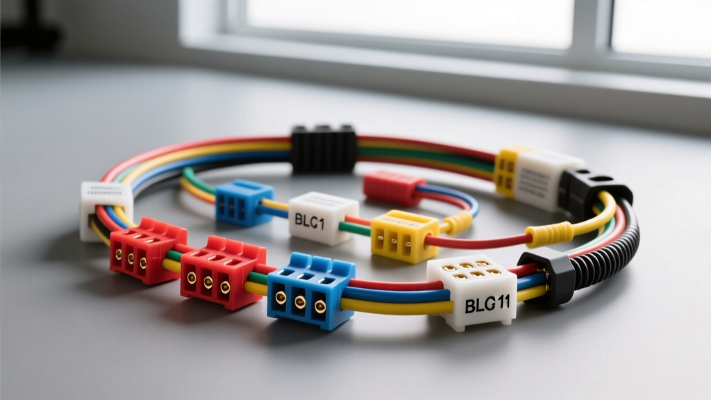
Understanding the BLT1 In-Tank Wiring Harness Architecture
The BLT1 in-tank wiring harness is a specialized, high-current electrical interface designed for custom fuel cells, EFI engine swaps, and high-performance in-tank fuel pump modules. Unlike standard OEM harnesses that often suffer from voltage drop when upgrading to 340 LPH or 450 LPH fuel pumps, the BLT1 architecture separates high-amperage pump circuits from low-amperage fuel level sender circuits. This isolation prevents electromagnetic interference (EMI) from corrupting the sensitive resistance signals sent to the ECU or dashboard gauge.
Troubleshooting an in-tank harness requires a methodical approach. Because the internal drop wires are submerged in fuel and the bulkhead connector is exposed to harsh undercarriage environments, failure modes typically manifest as voltage starvation, erratic gauge readings, or complete circuit opens. According to SAE J1128 standards for low-tension primary cable, wire insulation in fuel-submerged environments must resist hydrocarbon degradation. The BLT1 harness utilizes XLPE (Cross-Linked Polyethylene) or PTFE insulated drop wires internally to prevent the swelling and cracking associated with standard PVC wire in E85 and E10 ethanol blends.
BLT1 Harness Pinout and Wire Specification Chart
Before beginning the diagnostic flow, verify your harness against the standard BLT1 specification chart below. Using an undersized wire or misidentifying a pin will lead to immediate diagnostic errors.
| Circuit Function | Wire Color | AWG Size | Bulkhead Pin | Connector Type | Max Current / Spec |
|---|---|---|---|---|---|
| Pump Power (+12V) | Red | 10 AWG | Pin A | Metri-Pack 630 | 30A Continuous |
| Pump Ground | Black | 10 AWG | Pin B | Metri-Pack 630 | 30A Continuous |
| Sender Signal | Purple | 18 AWG | Pin C | Metri-Pack 280 | 0.5A Max (Signal) |
| Sender Ground | Black/White | 18 AWG | Pin D | Metri-Pack 280 | 0.5A Max (Signal) |
| Secondary Pump (Twin) | Red/White | 10 AWG | Pin E | Metri-Pack 630 | 30A Continuous |
Step-by-Step Troubleshooting Decision Tree
Follow this sequential diagnostic flow to isolate faults within the BLT1 in-tank wiring harness. Never bypass the bulkhead connector during testing, as doing so will mask high-resistance faults at the primary failure point.
Symptom 1: Fuel Pump Primes but Shuts Off or Runs Slow (Voltage Drop)
Diagnosis: High-amperage fuel pumps draw significant current (12A to 22A under load). If the pump runs slowly or the ECU cuts power due to low fuel pressure, you are experiencing voltage drop. A healthy 10 AWG circuit should exhibit less than 0.2V of drop across the entire power side, and less than 0.1V on the ground side.
- Step 1: Perform a Loaded Voltage Drop Test. Do not test with the key in the 'ON' position without the pump running. Backprobe Pin A (Red, 10 AWG) at the external bulkhead connector while the pump is actively running under load.
- Step 2: Measure the Drop. Place your multimeter's positive lead on the battery positive terminal and the negative lead on the backprobed Pin A. If the reading exceeds 0.3V, the fault is upstream of the harness (e.g., EFI relay, undersized chassis wiring, or corroded fuse block).
- Step 3: Test the Internal Drop. If the external power is good, drop the fuel tank or access the in-tank module. Measure voltage directly at the pump's positive spade terminal. Compare this to the voltage at the external Pin A. A difference greater than 0.2V indicates internal harness degradation or a loose internal crimp.
- The Fix: If the internal 10 AWG red wire is dropping voltage, the internal crimp to the pump pigtail has likely vibrated loose or suffered from micro-arcing. Cut the internal splice, strip back to clean XLPE copper, and re-crimp using a ratcheting crimper (e.g., Molex 64016-0201) with a sealed butt connector. Never solder in-tank pump connections, as solder wicks fuel via capillary action and becomes brittle from pump vibration.
Symptom 2: Erratic or Stuck Fuel Level Sender Readings
Diagnosis: The fuel level sender is a simple variable resistor (typically 240-33 ohms for GM applications or 0-90 ohms for Ford/Chrysler). Erratic gauge sweeps or a pegged 'Empty' reading usually indicate a floating ground, a broken 18 AWG signal wire, or an impedance mismatch.
- Step 1: Verify Sender Impedance Match. Before tearing into the harness, confirm your aftermarket fuel cell sender matches your gauge/ECU input. Sending a 240-33 ohm signal to a 0-90 ohm gauge will result in permanent 'Empty' or 'Full' readings. Reference the Holley EFI Hardware Manual for specific input scaling parameters if using an aftermarket ECU.
- Step 2: Isolate the Sender Ground. The BLT1 harness uses a dedicated 18 AWG Black/White wire (Pin D) for the sender ground. Do not rely on the fuel tank chassis ground. Measure resistance between Pin D at the bulkhead and the battery negative terminal. It should read less than 0.5 ohms. If higher, the external ground ring terminal is corroded.
- Step 3: Test the Signal Wire Continuity. Disconnect the battery. Measure resistance between Pin C (Purple) at the bulkhead and the ECU/Gauge input pin. An open loop (OL) indicates a broken 18 AWG wire, often caused by the wire chafing against the fuel tank sump baffle inside the tank.
- The Fix: If the internal 18 AWG purple wire is broken, it must be replaced with PTFE-insulated wire. Standard wire jackets will dissolve in fuel vapor over time, causing the copper to green-corrode and create a high-resistance path that mimics a 'low fuel' state.
Symptom 3: Complete Loss of Pump Power (No Prime)
Diagnosis: The pump does not prime when the key is cycled, and there is zero voltage reaching the in-tank module. This is typically an open circuit rather than a resistance issue.
- Step 1: Check the Inertia Switch and Relay. Many BLT1 harness installations integrate a safety inertia switch. Verify 12V is entering and exiting the switch. Listen for the EFI relay click. If the relay clicks but no power reaches Pin A, the relay contacts may be burnt.
- Step 2: Inspect the Bulkhead Connector Pins. The Metri-Pack 630 series pins used for the 10 AWG pump circuits are prone to 'push-out' if the secondary lock (TPA - Terminal Position Assurance) was not fully seated during assembly. Pull gently on the 10 AWG Red wire at the bulkhead. If the pin slides out of the plastic housing, the circuit is open.
- Step 3: Test the Internal Thermal Cutoff. Some high-flow in-tank modules feature an inline thermal breaker on the internal black ground wire. If the pump overheated due to a restricted fuel filter or running the tank dry, this breaker may have tripped or failed open.
- The Fix: If a pin has pushed out of the bulkhead connector, extract it using a Delphi Metri-Pack removal tool. Inspect the terminal tangs. If the tangs are flattened and will not lock into the housing housing cavity, cut off the terminal, strip the 10 AWG wire, and crimp on a new stamped brass Metri-Pack 630 terminal.
Advanced Diagnostic Testing: The Carbon Pile Load Test
Multimeters can be deceiving because they draw virtually zero amperage. A 10 AWG wire with only three strands of copper intact will still show 12.6V on a multimeter, but will instantly drop to 4V when a 15A fuel pump attempts to draw current through it. To definitively test the BLT1 in-tank harness without dropping the tank, perform a simulated load test.
Disconnect the harness from the fuel pump module and connect a 50-amp carbon pile tester (or a pair of 55W halogen headlight bulbs wired in parallel) across the external Pin A (Power) and Pin B (Ground). Apply the load to draw exactly 15 amps. Monitor the voltage at the load. If the voltage drops below 11.5V while the battery rests at 12.6V, your harness or upstream relay wiring has excessive resistance and must be repaired or replaced.
Common BLT1 Harness Failure Modes and Prevention
Preventing harness failure is vastly superior to troubleshooting a dead fuel system on the side of the road. The most common real-world failure modes for the BLT1 harness include:
- Vapor Zone Degradation: The area just below the top of the fuel tank (the vapor zone) contains highly corrosive ethanol vapors. If the internal harness wires are not routed tightly against the module body and secured with fuel-resistant zip ties, the vapors will permeate standard wire insulation within 6 to 12 months. Always use PTFE (Teflon) wire for internal drops.
- Improper Crimping: Using standard pliers to crush a Metri-Pack terminal destroys the terminal's internal bell-mouth geometry. This creates a high-resistance hotspot that will literally melt the plastic bulkhead connector housing under a 20A continuous load. Always use a ratcheting crimper calibrated for the specific AWG and terminal series.
- Missing Drip Loops: When routing the external harness from the bulkhead to the chassis, always create a 'drip loop' (a U-shaped bend below the connector). This prevents water and road grime from wicking directly into the bulkhead connector seals via capillary action, which causes green corrosion on the 18 AWG sender pins.
By adhering to this step-by-step troubleshooting flow and respecting the specific AWG and insulation requirements of in-tank fuel systems, you can ensure reliable, high-pressure fuel delivery for any EFI application.