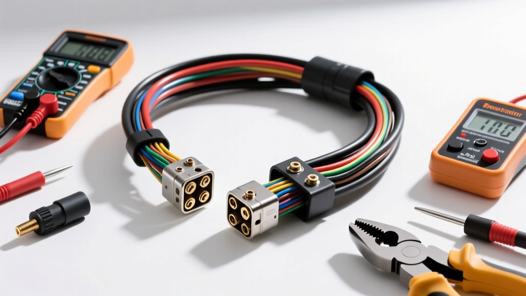
The Critical Role of the Crankshaft Position Sensor Wiring Harness
The crankshaft position sensor (CKP) is the primary timing reference for modern engine control modules (ECMs). It dictates ignition timing, fuel injection sequencing, and variable valve timing. When the crankshaft position sensor wiring harness degrades, the results are immediate and severe: extended cranking, erratic tachometer readings, random stalling, or a complete no-start condition. Because the CKP sensor is typically mounted low on the engine block near the harmonic balancer or oil pan, its wiring harness is subjected to extreme thermal cycling, high-frequency vibration, and exposure to road debris and oil.
For automotive technicians and DIY engine swappers, addressing a failing CKP harness requires a strategic approach. Simply splicing in standard primary wire without considering electromagnetic interference (EMI) shielding or proper terminal crimping will inevitably lead to signal dropouts. This comprehensive cost and tool requirements analysis breaks down the financial and technical realities of repairing, replacing, or fabricating a crankshaft position sensor wiring harness.
Cost Breakdown: OEM Replacement vs. Pigtail Repair vs. Custom Fabrication
When diagnosing a CKP circuit fault (such as OBD-II codes P0335, P0336, or P0339), the physical harness is often the culprit rather than the sensor itself. The insulation becomes brittle, or the internal copper strands fracture due to vibration. Below is a cost-benefit matrix detailing the three primary repair strategies.
| Repair Strategy | Estimated Cost | Pros | Cons & Limitations |
|---|---|---|---|
| Full OEM Engine Harness Replacement | $450 - $1,200+ | Factory fitment; includes all engine sensors; long-term reliability. | Prohibitively expensive; requires extensive teardown; overkill for isolated CKP damage. |
| OEM Pigtail / Connector Kit | $25 - $65 | Cost-effective; includes pre-crimped wires and correct weather seals. | Limited length (usually 6-12 inches); requires splicing into the main harness loom. |
| Custom Shielded Harness (DIY) | $15 - $35 | Exact length for engine swaps; superior EMI shielding; highly reliable. | Requires specialized crimping tools and technical knowledge of pinouts. |
For localized chafing or connector corrosion, the OEM Pigtail is the most logical choice. However, for LS swaps, custom turbo builds, or harnesses routed near high-tension ignition wires, fabricating a Custom Shielded Harness provides the best signal integrity.
Essential Tool Requirements for CKP Harness Repair
Repairing a crankshaft position sensor wiring harness is not a job for standard hardware store crimpers. The ECM relies on precise voltage thresholds, and a poor connection can introduce resistance that mimics a failing sensor. To execute a professional-grade repair, the following tools are mandatory:
1. Precision Ratcheting Crimpers
Most modern CKP sensors utilize Delphi Automotive Connection Systems (now Aptiv) Metri-Pack 150 or 280 series terminals. You must use a ratcheting crimper specifically designed for the terminal series. For Metri-Pack 150 terminals, a tool like the Delphi 12094428 or a high-quality aftermarket equivalent ensures the wire crimp and insulation crimp are formed to exact factory specifications, preventing the terminal from backing out of the connector housing under vibration.
2. Wire Stripping and Preparation Tools
CKP signal wires are typically 20 AWG. Using standard pliers will nick the copper strands, reducing the cross-sectional area and creating a hot spot. Use precision wire strippers calibrated for 20-22 AWG. If using shielded cable, a specialized coaxial or shielded cable stripper is required to peel back the braided copper shield without damaging the inner drain wire or the primary insulation.
3. Adhesive-Lined Dual-Wall Heat Shrink
Standard PVC heat shrink will melt when routed near exhaust manifolds. You must use Polyolefin dual-wall heat shrink with an inner layer of thermoplastic adhesive (e.g., Raychem SCL or 3M). When heated, the adhesive melts and flows into the wire strands, creating a waterproof, airtight seal that prevents capillary action from drawing oil or moisture into the harness loom.
4. Digital Multimeter (DMM) and Oscilloscope
While a DMM is sufficient for checking reference voltage and ground continuity, an automotive oscilloscope is the ultimate tool for verifying the CKP signal. A Fluke Electrical Diagnostic Guide emphasizes that back-probing the connector while the engine is cranking is the only way to definitively rule out harness resistance under load.
Technical Specifications: CKP Harness Pinouts & Wire Sizing
The physical construction of the crankshaft position sensor wiring harness depends heavily on the sensor type. Hall-effect sensors (common in GM LS/LT and Ford Coyote engines) require three wires: a power reference, a ground, and a digital signal. Variable Reluctance (VR) sensors (common in older Ford Modulars and Chrysler HEMI applications) use a two-wire magnetic pickup system.
Adhering to SAE J1128 Low Tension Primary Cable Standards, wire insulation must be rated for under-hood temperatures. GXL or TXL (cross-linked polyethylene) wire is mandatory due to its thin wall and high heat resistance.
| Application / Sensor Type | Pin / Function | Standard Wire Color (OEM Ref) | AWG Size & Cable Type |
|---|---|---|---|
| GM LS 58x (Hall Effect, 3-Way Delphi) | Pin A: 12V Reference | Pink or Red | 20 AWG TXL (Standard) |
| GM LS 58x (Hall Effect, 3-Way Delphi) | Pin B: Signal | Yellow or Blue | 20 AWG Shielded |
| GM LS 58x (Hall Effect, 3-Way Delphi) | Pin C: Low Reference (Ground) | Purple/White or Black | 20 AWG Shielded |
| Ford 4.6L/5.0L (VR Sensor, 2-Way) | Pin 1: Signal (+) | Light Blue / Yellow Tracer | 18 AWG Twisted Pair |
| Ford 4.6L/5.0L (VR Sensor, 2-Way) | Pin 2: Signal (-) | Light Blue / Pink Tracer | 18 AWG Twisted Pair |
The EMI Threat: Shielding vs. Twisted Pair
The most common mistake made when fabricating a custom crankshaft position sensor wiring harness is ignoring Electromagnetic Interference (EMI). The CKP signal is a low-voltage, high-frequency square wave (Hall) or a low-amplitude AC sine wave (VR). If the harness is routed near high-tension spark plug wires, alternator stators, or electric cooling fans, EMI can induce false voltage spikes in the signal wire. The ECM interprets these spikes as extra teeth on the reluctor wheel, causing severe timing retardation or engine misfires.
Hall Effect Sensors (Shielded Cable)
For 3-wire Hall sensors, use a 3-conductor shielded cable. The braided copper shield must be connected to a dedicated drain wire. Critical Expert Rule: The drain wire must be grounded at the ECM/PCM end ONLY. If you ground the shield at both the sensor and the ECM, you create a ground loop. The shield will act as an antenna for alternator whine and ground plane noise, completely defeating its purpose.
Variable Reluctance Sensors (Twisted Pair)
VR sensors do not typically use shielded cable; instead, they rely on a twisted pair. The two signal wires must be twisted together at a rate of 12 to 16 twists per foot. This geometry ensures that any external magnetic interference induces an equal and opposite voltage in both wires, which the ECM's differential amplifier cancels out as common-mode noise.
Step-by-Step Cost-Effective Repair Strategy
- Isolate the Fault: Use a multimeter to verify the 12V reference and ground at the sensor connector with the key in the 'ON' position. If power and ground are present but the signal is erratic, inspect the harness for chafing against the oil pan or timing cover.
- Excise the Damage: Cut the harness back at least 4 inches past the visible damage. Copper oxidation can wick up inside the insulation; cutting too close to the damaged area will leave high-resistance wire in the circuit.
- Prepare the Terminals: If replacing the connector, strip the new GXL/TXL wire to the exact depth specified by the terminal manufacturer. Insert the wire into the ratcheting crimper and cycle the tool until it releases.
- Seal and Protect: Slide adhesive-lined heat shrink over the splice joints. Apply heat evenly until the adhesive purges slightly from the ends. Wrap the entire repaired section in high-temperature harness tape (e.g., Tesa 51036 PET fleece tape) to prevent future chafing.
- Verify Signal Integrity: Back-probe the signal wire and crank the engine. A healthy Hall sensor will show a clean 0V to 5V (or 12V) square wave. A healthy VR sensor will show an AC voltage that increases in amplitude and frequency as engine RPM rises.
Conclusion
Repairing or fabricating a crankshaft position sensor wiring harness is a high-stakes procedure where cutting corners leads to catastrophic drivability issues. While a full OEM harness replacement is cost-prohibitive for most, utilizing OEM pigtails or fabricating a custom harness using SAE-spec GXL wire, proper Delphi terminals, and correct EMI shielding techniques offers a reliable, cost-effective solution. By investing in the correct ratcheting crimpers and understanding the critical differences between shielded drains and twisted pairs, you ensure the ECM receives the pristine timing data required for optimal engine performance.