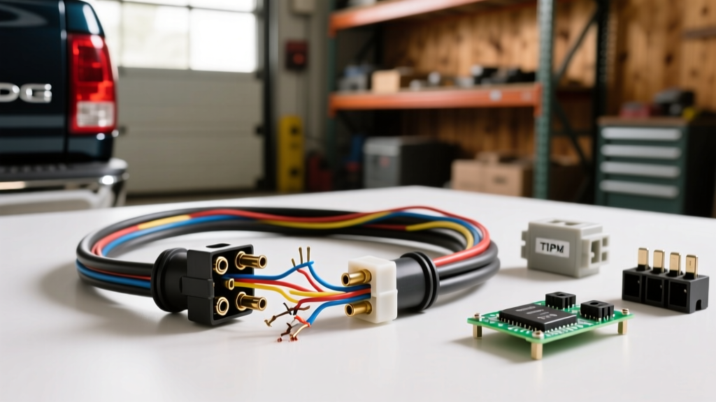
Diagnosing the Dodge Ram Tail Light Wiring Harness: A Step-by-Step Flow
Electrical gremlins in the rear lighting circuit of 3rd and 4th generation Dodge Rams (2002-2018) are notoriously frustrating. Whether you are dealing with a dead left turn signal, hyper-flashing, or a complete loss of trailer running lights, the root cause usually traces back to the Dodge Ram tail light wiring harness or the Totally Integrated Power Module (TIPM). This troubleshooting flow is designed for automotive technicians and advanced DIYers to systematically isolate shorts, open circuits, and TIPM relay failures without throwing unnecessary parts at the truck. By following this structured diagnostic path, you can pinpoint the exact failure node, from the front power distribution center to the rear 7-way RV receptacle.
Phase 1: Preliminary Symptom Isolation Decision Tree
Before unbolting the spare tire or pulling bed bolts, define the exact failure mode. The Ram's rear lighting system splits into two primary circuits: the chassis body harness and the trailer tow package harness. Use this decision tree to narrow your focus:
- Symptom A: Left/Right Tail Light out, but trailer lights work. Action: Fault is downstream of the rear body-to-frame junction block (often corrosion in the 14-pin intermediate connector or a bad bulb socket ground).
- Symptom B: No trailer running lights, but truck tail lights work. Action: Fault is isolated to the 7-way RV receptacle pigtail, the trailer tow wiring adapter, or the TIPM trailer tow running light relay.
- Symptom C: Complete loss of both stop and turn signals on one side. Action: Suspect a broken 16 AWG GXL wire at the frame-to-bed transition or a failed TIPM internal solid-state relay.
- Symptom D: Hyper-flashing with standard incandescent bulbs installed. Action: Check for a partial short to ground causing high current draw, or a failing TIPM logic board sensing a false 'bulb out' condition.
Phase 2: Physical Harness Routing & Chafe Inspection
The OEM Dodge Ram tail light wiring harness takes a punishing route from the cabin, through the frame rail, and down to the rear bumper. The most critical failure point on 1500, 2500, and 3500 models is the spare tire hoist area. Over time, road debris, salt, and vibration cause the harness loom to degrade. The harness rubs against the steel crossmember supporting the spare tire, wearing through the corrugated split loom and eventually shorting the 16 AWG stop/turn wires directly to the chassis ground.
Inspection Steps:
- Lower the spare tire completely to gain unobstructed access to the hoist mechanism and surrounding frame rails.
- Trace the main chassis harness from the driver-side frame rail toward the rear bumper. Follow the loom as it transitions over the rear axle.
- Inspect the section where the harness crosses the rear axle and the spare tire crossmember. Look for melted electrical tape, exposed copper, or green copper oxide (verdigris) indicating moisture ingress and capillary wicking.
- Check the 14-way intermediate connector (located near the fuel tank on 1500 models, or further forward on 2500/3500 diesel models due to the DEF tank or auxiliary fuel tank). Disconnect the connector, pull back the weather-pack seal, and inspect for pushed-out pins, terminal fretting, or water intrusion.
Phase 3: Ground Node Verification (G201 & G202)
A vast majority of 'bad harness' diagnoses are actually ground failures. The rear lighting circuits rely heavily on ground nodes G201 and G202, typically located on the inner frame rails near the rear bumper or behind the rear wheel wells. When these ground studs corrode, the tail lights will back-feed through the license plate lamps or the trailer circuit, causing dim lights or erratic flashing.
- Locate the ground stud using a factory service manual wiring diagram for your specific model year.
- Remove the retaining nut (usually 8mm or 10mm) and pull the ground ring terminals off the stud.
- Clean the frame metal and the ring terminals with a wire wheel until bare, shiny steel is exposed.
- Reattach the terminals, apply a coat of dielectric grease over the connection to prevent future oxidation, and torque the nut to 25 in-lbs.
Phase 4: OEM Connector Pinout & Multimeter Testing
When testing the Dodge Ram tail light wiring harness, you must verify continuity and voltage under load. Use a digital multimeter (DMM) and a load-testing probe to simulate amperage draw. A standard test light can sometimes bridge a high-resistance corrosion point and give a false positive. Below is the standard pinout and wire specification for the Ram 7-Way Trailer Connector and corresponding tail light feeds, based on SAE J560 standards for heavy-duty vehicle connectors and standard RV wiring conventions.
| Pin / Circuit | Function | OEM Wire Color (Typical) | Wire Gauge (AWG) |
|---|---|---|---|
| Pin 1 | Left Turn / Stop | Yellow | 16 AWG (GXL) |
| Pin 2 | Reverse Lights | Light Green / Purple | 16 AWG (GXL) |
| Pin 3 | Ground (Chassis) | White / Black | 12 AWG (SGT) |
| Pin 4 | Running / Marker Lights | Brown | 16 AWG (GXL) |
| Pin 5 | Right Turn / Stop | Green | 16 AWG (GXL) |
| Pin 6 | 12V Auxiliary / Battery | Red / Black | 12 AWG (SGT) |
| Pin 7 | Electric Trailer Brakes | Blue | 12 AWG (SGT) |
Testing Protocol:
- Voltage Drop Test: Set your DMM to DC Volts. Place the black lead on a known good chassis ground (bare metal on the frame) and the red lead on the Pin 4 (Brown) wire at the 7-way connector with the headlights ON. A reading below 11.5V indicates excessive resistance in the harness or a failing TIPM relay.
- Continuity Test: Disconnect the battery. Set the DMM to Ohms. Test from the rear lamp socket ground to the main chassis ground. Resistance should be less than 0.5 ohms. Anything higher indicates a corroded ground node or a compromised harness ground wire.
Phase 5: TIPM (Totally Integrated Power Module) Diagnostics
On 2006-2011 Dodge Rams, the TIPM acts as the central brain for the lighting circuits. It uses internal solid-state relays and micro-controllers to manage the tail lights and trailer tow circuits. A very common failure mode is the internal micro-solder joints cracking on the trailer running light relay, resulting in zero voltage output on the Brown wire, even if the truck's bed lights work perfectly.
Before replacing the expensive TIPM or attempting a complex TIPM bypass harness installation, verify the inputs. Using an advanced OBD2 scan tool capable of reading TIPM data streams, command the 'Trailer Tow Running Lamps' ON. If the scan tool shows 'Relay Commanded: ON' but you have no voltage at Pin 4 of the 7-way connector, the TIPM internal relay is confirmed dead. In these cases, installing an external relay bypass harness that draws power directly from the battery and uses the TIPM's low-current signal wire to trigger the relay is the most reliable, permanent fix.
Phase 6: LED Upgrade Complications and PWM Signals
Many Dodge Ram owners upgrade to LED tail lights or LED trailer markers to improve visibility and longevity. However, the Dodge Ram tail light wiring harness and TIPM are designed around the electrical resistance of incandescent bulbs. The TIPM sends a Pulse Width Modulated (PWM) signal or a brief high-voltage 'bulb check' pulse upon startup to verify circuit continuity.
Because LEDs draw minimal current, the TIPM interprets this as a 'blown bulb' and will either cut power to the circuit entirely or cause the LEDs to strobe rapidly (hyper-flashing). If you are troubleshooting a harness that was recently modified for LEDs, you must install CANbus-compatible load resistors (typically 6-ohm, 50-watt resistors) wired in parallel with the LED harness to simulate the 2.1-amp draw of a standard 1157 incandescent bulb. Ensure these resistors are mounted to bare metal, as they generate extreme heat during operation and will melt standard wire loom or plastic bumper fascia.
Phase 7: Executing the Repair or Harness Replacement
Once the fault is isolated to a specific segment of the Dodge Ram tail light wiring harness, you have two primary repair paths:
Option A: Splice and Seal (Minor Chafing)
If the damage is localized to a single 16 AWG wire rubbing on the spare tire hoist, cut out the damaged section. Use a heat-shrink butt connector with an adhesive-lined interior (meeting SAE J1128 environmental sealing standards for low-tension primary cable). Do not use standard vinyl electrical tape or non-adhesive crimps. Without the adhesive seal, capillary action will wick moisture into the copper strands, causing green corrosion to migrate under the wire insulation within six months, leading to an invisible open circuit.
Option B: Full Pigtail or Harness Kit Replacement
If the 14-pin intermediate connector is melted, or if multiple wires are compromised, replace the entire rear body harness extension kit. Mopar offers OEM replacement pigtails for select 7-way receptacles and intermediate plugs. When installing a new harness kit:
- Apply a high-quality dielectric grease (such as Nyogel 760G) to all connector cavities before mating to prevent galvanic corrosion.
- Wrap the harness in Tesa tape or friction tape to prevent future squeaks and provide a secondary abrasion barrier against the steel frame.
- Secure the harness to the frame using UV-resistant zip ties or OEM push-clips, ensuring a minimum 2-inch clearance from the exhaust system, the spare tire hoist cables, and any moving suspension components.
Summary
Troubleshooting the Dodge Ram tail light wiring harness requires a methodical, step-by-step approach. By separating the chassis lighting from the trailer tow circuits, inspecting the notorious spare tire hoist chafe points, verifying ground nodes, and understanding the limitations of the TIPM, you can accurately diagnose the fault. Always rely on proper wire gauges, sealed connectors, and adherence to SAE standards to ensure your electrical repair outlasts the truck itself.