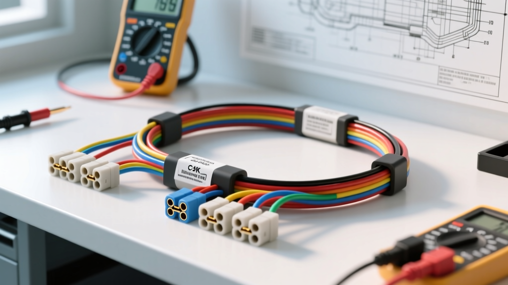
How to Find a Short in a Wiring Harness: The Step-by-Step Troubleshooting Flow
Tracking down an electrical short in an automotive wiring harness is one of the most frustrating challenges in vehicle diagnostics and engine swap fabrication. Whether you are debugging a custom LS swap harness, troubleshooting a parasitic draw on a daily driver, or repairing a chafed OEM loom near the firewall, a methodical approach is mandatory. Guessing leads to cut wires, melted insulation, and potentially destroyed control modules. This guide provides a definitive, step-by-step troubleshooting flow to help you isolate and repair shorts to ground, shorts to power, and cross-circuit shorts safely and efficiently.
Understanding the Three Types of Automotive Shorts
Before grabbing a multimeter, you must identify the nature of the fault. Automotive electrical systems typically suffer from three distinct short circuit conditions:
- Short to Ground: The most common fault. A positive voltage wire (e.g., a 12V ignition feed) breaches its insulation and contacts the chassis or engine block. This creates a path of least resistance, causing a massive current spike that instantly blows the circuit fuse.
- Short to Power: A ground wire or a switched circuit unintentionally contacts a constant 12V battery feed. This often results in backfeeding, causing modules to stay awake, draining the battery, or frying solid-state drivers inside an ECU or TCM.
- Short to Another Circuit (Cross-Circuit): Two adjacent wires inside a harness or connector melt together. For example, a 5V sensor reference wire (typically Gray or Light Green) shorting against a 12V injector driver wire. This will instantly destroy the ECU's internal 5V voltage regulator.
Required Diagnostic Tooling
To properly execute this troubleshooting flow, you must abandon outdated methods. Never use a standard incandescent test light to probe modern automotive circuits. Test lights draw significant current and can easily trigger airbag (SRS) deployment or destroy sensitive CAN bus transceivers. Instead, utilize the following tools:
- High-Impedance Digital Multimeter (DMM): A DMM with a minimum 10-Megaohm input impedance (such as the Fluke 87V or 88V) is required to prevent loading the circuit and to provide accurate resistance and voltage drop readings.
- Tone Generator and Inductive Probe: Essential for tracing wires hidden deep inside dash harnesses or under carpet without piercing insulation.
- Breakout Boxes / Pin-Probes: Used to back-probe Weather-Pack, Deutsch, and Metri-Pack connectors without spreading the brass or copper terminal pins, which causes future corrosion and voltage drop.
The 6-Step Isolation Flow
Follow this sequential decision tree to isolate the exact location of the short circuit. This flow assumes you are diagnosing a blown fuse (Short to Ground).
Step 1: Pull the Schematic and Identify the Circuit Topology
Never diagnose a circuit blind. Obtain the OEM wiring diagram or your aftermarket harness schematic. Identify the exact fuse rating (e.g., 15A ECM IGN), the wire color (e.g., Pink 14 AWG), and every intermediate connector (e.g., C100 bulkhead, C200 dash-to-engine) between the fuse box and the final load (ECU, fuel pump, solenoid).
Step 2: Disconnect the Battery and the Load
Disconnect the negative battery terminal. Next, disconnect the load component at the end of the circuit. Critical Warning: If you test continuity to ground while the ECU or module is still plugged in, you will read a false short through the module's internal circuitry, leading you to misdiagnose a perfectly good wiring harness.
Step 3: Establish the Baseline Continuity Test
Set your DMM to the Ohms/Continuity setting. Place the black probe on a known, bare-metal chassis ground. Insert the red probe into the load side of the blown fuse terminal in the fuse box. If the meter reads 'OL' (Open Loop) or infinite resistance, the short is intermittent or has melted completely open. If the meter reads near 0.00 Ohms and beeps, you have confirmed a hard short to ground.
Step 4: Divide and Conquer (The Halving Method)
Locate the physical midpoint of the harness run. For an engine swap harness, this is usually the firewall bulkhead connector. Disconnect the bulkhead connector. Re-test the continuity at the fuse box.
- If the short disappears (reads OL): The fault is located in the engine bay harness (downstream of the bulkhead).
- If the short remains (reads 0.00 Ohms): The fault is located in the cabin/dash harness (upstream of the bulkhead).
Step 5: The Manipulation and Wiggle Test
Once you have isolated the short to a specific 3-foot section of harness, leave your DMM connected and set to continuity with the audible beep enabled. Aggressively wiggle, bend, and twist the harness. Pay close attention to areas where the loom passes through sheet metal, near exhaust headers, or around steering column linkages. The exact moment the DMM beeps, you have found the physical pinch point or chafe mark.
Step 6: Pinpoint Connector Pin Push-Out or Capillary Wicking
If the short is isolated to a connector (like a GM E38 ECU X1 connector or a Ford C100), inspect the cavity for 'green death' (copper oxide corrosion). Water can wick through the wire insulation capillary action, creating a conductive bridge between a 12V pin and a ground pin inside the plastic housing. Use electrical contact cleaner and a fiber optic pick to clear the debris.
Real-World Failure Modes in Swaps and OEM Harnesses
When learning how to find a short in a wiring harness, recognizing common failure patterns saves hours of diagnostic time. Here are frequent culprits observed in the field:
- GM LS / LT Engine Swaps: The main ignition feed (typically Pink, 14 AWG or 12 AWG) is often routed too close to the back of the aluminum cylinder heads or exhaust manifolds. The heat melts the cross-linked polyethylene (XLPE) insulation, shorting the 12V feed to the engine block and blowing the main IGN fuse.
- Ford Coyote / Modular Swaps: The alternator sense wire and CAN bus lines (often Gray/Orange, 18 AWG) are highly susceptible to chafing against the aluminum bracketry near the passenger side valve cover. Furthermore, the C100 bulkhead connector is notorious for pin push-out if the secondary lock (TPA) is not fully seated during harness assembly.
- Aftermarket Relay Blocks: In custom-fabricated harnesses, using standard 30A Bosch-style relays without sealed Deutsch DT connectors often leads to water ingress. The resulting electrolysis bridges the 30 (Battery) and 87 (Load) terminals, causing a dead short.
Wire Gauge and Fuse Specification Chart
Properly sizing your fuse to the wire gauge is the only way to protect the harness from melting during a short circuit event. Refer to this baseline chart based on SAE J1128 standards for low-tension primary cable.
| Wire Gauge (AWG) | Typical Application | Max Continuous Amps | Recommended Fuse | Expected Resistance (per 10ft) |
|---|---|---|---|---|
| 18 AWG | Sensors, CAN Bus, 5V Ref | 7A - 10A | 5A or 7.5A | ~0.064 Ohms |
| 14 AWG | Ignition Feeds, Injectors | 15A - 20A | 15A or 20A | ~0.025 Ohms |
| 10 AWG | Fuel Pumps, High-Amp Solenoids | 30A | 25A or 30A | ~0.010 Ohms |
| 8 AWG | Main ECU Power, Starter Signal | 40A - 50A | 40A | ~0.006 Ohms |
| 4 AWG | Battery Feed, Alternator Output | 80A - 100A | Mega-Fuse / ANL | ~0.002 Ohms |
Proper Repair Protocols
Once the short is located, the repair must be executed to OEM standards. Never use twist-on wire nuts or standard vinyl electrical tape under the hood; heat and vibration will guarantee a repeat failure. For harness repairs, strip the wire using precision gauged strippers to avoid nicking the copper strands. Use a ratcheting crimp tool to apply adhesive-lined heat shrink butt connectors (such as Delphi Packard or Molex crimp sleeves). Apply heat until the adhesive sealant purges from the ends of the shrink tube, ensuring a completely waterproof seal. Finally, wrap the repaired section in friction tape (Tesa tape) or split-loom conduit to prevent future chafing against the chassis.
Authoritative References
- SAE International - J1128: Low Tension Primary Cable
- Fluke Corporation - Automotive Electrical Troubleshooting Guide
- ASE Certification L1 Advanced Engine Performance Specialist Diagnostic Standards