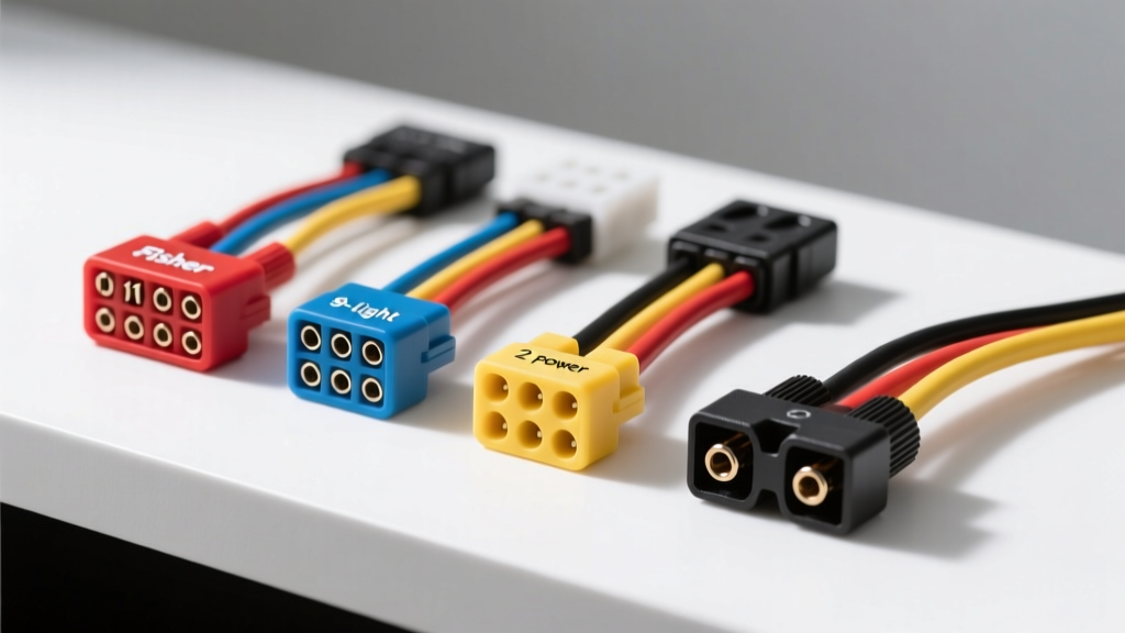
Fisher 3 Plug Wiring Harness Architecture
The Fisher 3 plug wiring harness system is the foundational electrical architecture for many of the most widely deployed snowplows in North America, specifically the Minute Mount 2 and Ultramount models. Unlike newer multiplex CAN-bus systems that condense signals into digital packets, the classic 3-plug setup relies on dedicated, analog, relay-driven circuits. This separation of power, lighting, and hydraulic control provides a robust, easily diagnosable framework for fleet mechanics and owner-operators.
Understanding the exact pinout, wire gauge, and color codes of the Fisher 3 plug wiring harness is critical for troubleshooting voltage drops, replacing damaged vehicle-side pigtails, and fabricating custom cab-pass-throughs. The system is physically divided into three distinct weather-sealed connectors located at the front of the truck: a 2-pin high-amperage power plug, a 9-pin lighting plug, and an 11-pin hydraulic control plug.
Plug 1: Heavy-Duty Power Circuit (2-Pin)
The 2-pin connector is responsible for delivering high-current 12V DC power directly from the vehicle battery to the plow’s hydraulic motor solenoid. Because the hydraulic pump can draw upwards of 150 amps under peak load (such as when lifting a fully loaded, steel-edged plow), this circuit demands heavy-gauge wiring and minimal resistance. The connector utilizes large, silver-plated copper contacts to prevent thermal meltdown during sustained operation.
Plug 2: Lighting and Auxiliary Circuit (9-Pin)
The 9-pin lighting harness bridges the truck’s OEM headlight, turn signal, and marker light circuits to the plow’s lighting assembly. This plug handles moderate current loads (typically 5A to 15A per circuit) and relies on the truck’s body control module (BCM) or standard relays to trigger the plow lamps. Proper isolation diodes or smart relay modules are often integrated into the vehicle-side harness to prevent back-feeding into the truck’s sensitive CAN-bus lighting networks.
Plug 3: Hydraulic Control Circuit (11-Pin)
The 11-pin control plug carries low-current signal voltages from the in-cab joystick or handheld controller to the hydraulic valve coils on the plow. These circuits trigger the directional spool valves (lift, lower, angle left, angle right). Because these are inductive loads, the harness must withstand flyback voltage spikes when the valve coils are de-energized, necessitating built-in suppression diodes at the coil connectors.
Technical Pinout and Wire Gauge Specifications
The following tables detail the standard pin assignments, wire colors, and American Wire Gauge (AWG) requirements for the classic Fisher 3 plug wiring harness. All wire specifications align with SAE J1128 standards for low-tension primary automotive cable, requiring cross-linked polyethylene (XLPE) insulation for high-temperature and chemical resistance.
Table 1: 2-Pin Power Connector Specifications
| Pin | Function | Wire Color | AWG Size | Circuit Notes |
|---|---|---|---|---|
| A | Motor Power (+12V) | Red / Black Stripe | 8 AWG | Connects directly to battery via 200A mega fuse. |
| B | Motor Ground | Black / White Stripe | 8 AWG | Must terminate to clean, bare-metal chassis ground. |
Table 2: 9-Pin Lighting Connector Specifications
| Pin | Function | Wire Color | AWG Size | Circuit Notes |
|---|---|---|---|---|
| 1 | Right Turn Signal | Green | 16 AWG | Flashing load; verify BCM compatibility. |
| 2 | Left Turn Signal | Yellow | 16 AWG | Flashing load; verify BCM compatibility. |
| 3 | Lighting Ground | Black | 14 AWG | Dedicated ground return for lighting circuits. |
| 4 | Marker / Clearance | Brown | 16 AWG | Runs with parking lights; 5A max draw. |
| 5 | High Beam | White | 14 AWG | Halogen draws ~5A; LED draws <1A. |
| 6 | Low Beam | Red / White | 14 AWG | Primary driving illumination circuit. |
| 7 | Not Used (Spare) | N/A | N/A | Reserved for auxiliary strobes or work lights. |
| 8 | Not Used (Spare) | N/A | N/A | Reserved for auxiliary accessories. |
| 9 | Secondary Ground | Black | 14 AWG | Redundant ground to prevent voltage drop. |
Table 3: 11-Pin Hydraulic Control Connector Specifications
| Pin | Function | Wire Color | AWG Size | Circuit Notes |
|---|---|---|---|---|
| 1 | Ignition 12V Source | Red | 16 AWG | Switched 12V; powers controller logic. |
| 2 | Control Module Ground | Black | 16 AWG | Logic ground; do not share with motor ground. |
| 3 | Motor Solenoid Trigger | White / Red | 14 AWG | Activates the main hydraulic pump contactor. |
| 4 | Lift Valve Coil | Blue / White | 16 AWG | Raises the plow; high inductive spike on release. |
| 5 | Lower Valve Coil | Orange / White | 16 AWG | Lowers the plow; gravity assist requires minimal flow. |
| 6 | Angle Left Valve | Green / White | 16 AWG | Activates left-angling spool valve. |
| 7 | Angle Right Valve | Brown / White | 16 AWG | Activates right-angling spool valve. |
| 8 | Joystick Ground | Black | 18 AWG | Dedicated signal ground for in-cab controller. |
| 9 | Diagnostic Feedback | Yellow | 18 AWG | Used by handheld testers for fault code retrieval. |
| 10 | Spare / Aux | Purple | 18 AWG | Often used for aftermarket hitch light triggers. |
| 11 | Spare / Aux | Gray | 18 AWG | Reserved for future system expansion. |
Common Failure Modes and Diagnostic Procedures
When servicing the Fisher 3 plug wiring harness, technicians must move beyond simple visual inspections and utilize a Digital Multimeter (DMM) to identify hidden resistance faults. Below are the most common field failures and their diagnostic pathways.
Symptom: Plow Lifts Slowly or Motor Bogs Down
- Cause: Severe voltage drop on the 2-pin power circuit, typically due to corrosion inside the Pin A/B weather seals or a degraded battery-to-solenoid cable.
- Diagnostic Fix: Set your DMM to DC Voltage. Connect the red probe to the battery positive terminal and the black probe directly to the plow motor positive stud (bypassing the harness). Engage the lift function. If the DMM reads a drop greater than 0.5V, the 8 AWG power harness or its terminal crimps are compromised. Reference Madelectrical.com's voltage drop guidelines to verify acceptable thresholds for high-amperage DC circuits.
Symptom: Plow Angles Erratically or Valves Chatter
- Cause: High resistance or a partial short on the 11-pin control circuit (Pins 4 through 7), often caused by chafing where the harness passes through the firewall or rubs against the truck's suspension components.
- Diagnostic Fix: Disconnect the 11-pin plug at the grill. Perform a continuity test from the cab-side controller plug to the grill-side pigtail. Wiggle the harness aggressively during the test. An intermittent open circuit indicates broken copper strands inside an intact insulation jacket—a common failure point in cold-weather environments where XLPE insulation stiffens.
Symptom: Plow Lighting Flickers or Truck Dash Throws Bulb-Out Warnings
- Cause: The 9-pin lighting harness is back-feeding voltage into the truck’s CAN-bus system, or the ground pins (3 and 9) have developed surface corrosion, forcing return current through the truck's chassis.
- Diagnostic Fix: Verify that the vehicle-side harness utilizes a smart relay isolation module. If the truck uses PWM (Pulse Width Modulation) for lighting control, standard diodes will fail; an active PWM-to-DC converter relay kit must be spliced into the 9-pin lighting feed.
Harness Routing and Weatherproofing Best Practices
The longevity of a Fisher 3 plug wiring harness is dictated by its installation quality. Snowplow environments expose wiring to extreme thermal cycling, road salt (calcium chloride), and high-pressure vibration.
- Dielectric Grease Application: Never mate the 2-pin, 9-pin, or 11-pin connectors dry. Apply a lithium-based, marine-grade dielectric grease (such as Nyogel 760G or equivalent) to the female terminal cavities. This displaces moisture and prevents galvanic corrosion between the brass and silver-plated contacts. Avoid standard silicone greases, which can swell certain rubber seal materials over time.
- Firewall Pass-Through: When routing the 11-pin control and 9-pin lighting harnesses into the cab, never drill a new hole without installing a rubber grommet. Use a stepped grommet and secure the harness with UV-resistant zip ties, leaving a drip loop immediately outside the firewall to prevent water from tracking along the wire jacket into the cab.
- Splicing and Termination: If a wire requires repair in the field, do not use twist-on connectors or electrical tape. Strip the wire, use an adhesive-lined, dual-wall heat shrink crimp terminal, and apply heat until the adhesive seals the wire jacket. According to Fisher Engineering Service Manuals, any exposed copper in the engine bay will wick moisture via capillary action, leading to internal harness corrosion within a single winter season.
By adhering to these pinout specifications, AWG requirements, and diagnostic protocols, fleet technicians can drastically reduce plow downtime and ensure reliable hydraulic and lighting operation throughout the harshest winter conditions.