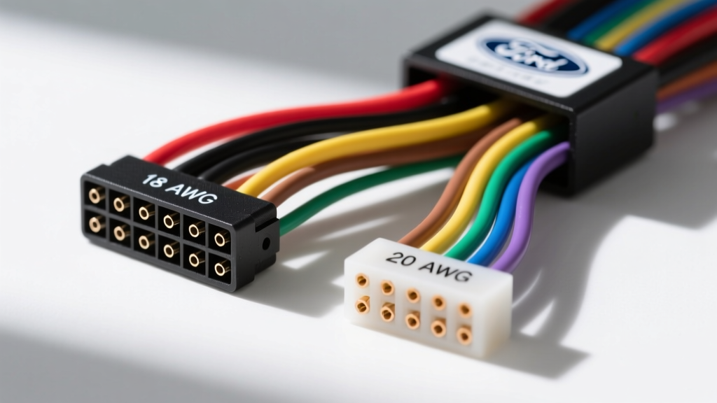
Introduction to Ford Audio Architecture and Harness Evolution
When performing an audio upgrade, diagnosing a dead head unit, or executing a custom console swap, understanding the factory wiring harness Ford radio wire harness color codes is the critical first step. Ford's automotive electrical architecture has evolved drastically over the last three decades. What began as simple analog 12-volt circuits powering single-DIN receivers has transformed into complex, multiplexed data networks utilizing CAN-bus, LIN-bus, and LVDS (Low-Voltage Differential Signaling) to communicate between the Audio Control Module (ACM) and the Front Display Interface Module (FDIM).
This complete wiring diagram walkthrough breaks down the exact pin configurations, wire color codes, and AWG specifications for both the classic Ford 16-pin oval connector and the modern 24-pin/12-pin SYNC-era connectors. Whether you are integrating an aftermarket adapter or fabricating a custom engine-swap harness that retains factory steering wheel controls, these specifications will ensure a safe, reliable, and fully functional electrical connection.
Classic Ford 16-Pin Harness (1998–2012 Platforms)
For platforms like the 1998–2012 Ford F-150, Mustang, and Ranger, the factory radio harness primarily utilizes a 16-pin 'D-shaped' or oval connector. This harness relies on traditional analog 12V power, switched accessory, and discrete speaker outputs. According to Motorcraft Service Documentation, this generation does not require data-bus decoding for basic power and speaker functions, making aftermarket integration relatively straightforward.
16-Pin Connector Pinout and Color Codes
| Pin | Wire Color | Function | AWG | Notes |
|---|---|---|---|---|
| 1 | Light Green/Purple | Switched 12V (Accessory) | 16 AWG | Hot only in RUN/ACC |
| 2 | Yellow | Constant 12V (Memory) | 14 AWG | Fused at battery junction box |
| 3 | Black | Chassis Ground | 14 AWG | Must have < 0.1 ohm to chassis |
| 4 | Orange | Illumination | 20 AWG | 12V when parking lights are ON |
| 5 | Orange/Black | Dimmer Signal | 22 AWG | PWM or variable voltage signal |
| 6 | Not Used | — | — | Blank cavity |
| 7 | White/Black | Left Front Speaker (+) | 18 AWG | Standard EIA color code |
| 8 | Orange/Black | Left Front Speaker (-) | 18 AWG | Do not ground negative wires |
| 9 | White/Red | Right Front Speaker (+) | 18 AWG | Standard EIA color code |
| 10 | Brown/Red | Right Front Speaker (-) | 18 AWG | Bridged output on premium amps |
| 11 | White/Green | Left Rear Speaker (+) | 18 AWG | Standard EIA color code |
| 12 | Brown/Yellow | Left Rear Speaker (-) | 18 AWG | Check for factory subwoofer tap |
| 13 | White/Violet | Right Rear Speaker (+) | 18 AWG | Standard EIA color code |
| 14 | Brown/Violet | Right Rear Speaker (-) | 18 AWG | Standard EIA color code |
| 15 | Light Blue/White | Power Antenna Trigger | 20 AWG | 12V output when AM/FM selected |
| 16 | Light Green | Amp Turn-On (Premium) | 20 AWG | Present only with Mach/Sony audio |
Modern Ford SYNC 24-Pin & 12-Pin Harness (2015–Present)
The introduction of SYNC 3 and the APIM (Accessory Protocol Interface Module) radically changed the factory wiring harness Ford radio wire harness color codes. In modern F-150s, Explorers, and Mustangs, the 'radio' is actually split into the ACM (usually hidden behind the dash or under a seat) and the FDIM (the touchscreen). The primary harness is a 24-pin TE Connectivity / Molex MX150 sealed connector, accompanied by a separate 12-pin speaker connector and an LVDS video cable.
Primary 24-Pin ACM / APIM Connector Pinout
| Pin | Wire Color | Function | AWG | Network / Protocol |
|---|---|---|---|---|
| 1 | White/Blue | MS-CAN High | 20 AWG | SAE J2284-2 (500 kbps) |
| 2 | White | MS-CAN Low | 20 AWG | SAE J2284-2 (500 kbps) |
| 3 | Gray/Orange | LIN Bus | 22 AWG | Local Interconnect Network |
| 7 | Violet/Orange | Constant 12V (Battery) | 14 AWG | Fused at BCM (Body Control Module) |
| 13 | Black/Green | Logic / Power Ground | 14 AWG | Central ground point G204 |
| 14 | White/Red | Switched 12V (ACC Delay) | 16 AWG | Controlled by BCM via relay |
| 18 | Green/Orange | Reverse Gear Trigger | 20 AWG | 12V when transmission is in 'R' |
| 21 | Shield Drain | Data Network Shield | 22 AWG | Prevents EMI on CAN lines |
Note: Speaker outputs on modern Ford premium systems (Sony/B&O) are amplified. The 12-pin connector carries low-level differential audio signals from the ACM to the DSP, not standard high-level speaker outputs. Bypassing the factory DSP requires specialized adapter harnesses to intercept pre-amplified signals.
Wire Gauge (AWG) Specifications and Current Limits
Adhering to proper SAE wiring standards is vital when repairing or extending Ford harnesses. Using undersized wire for constant 12V circuits leads to voltage drop, causing the ACM to reboot during engine cranking. Conversely, oversized wire in delicate CAN-bus circuits can damage the terminal pins inside the Molex MX150 connector.
- 14 AWG (Battery/Ground): Rated for up to 15A continuous. Used for the main memory and ground circuits. Must be crimped with insulated barrel connectors and sealed with adhesive heat shrink.
- 16 AWG (Accessory/Illumination): Rated for up to 10A. Used for switched power and antenna triggers.
- 18 AWG (Speaker Outputs): Used for classic high-level analog speaker outputs. Keep runs under 8 feet to prevent high-frequency attenuation.
- 20-22 AWG (Data/CAN/LIN): Strictly for multiplexed data. Never use these for power delivery. Twisted pair routing is mandatory for Pins 1 and 2 to maintain the 120-ohm impedance required by the CAN-bus physical layer.
Troubleshooting Common Factory Harness Failures
When diagnosing electrical faults using the factory wiring harness Ford radio wire harness color codes, follow this systematic decision tree to isolate the failure point without unnecessarily replacing expensive OEM modules.
Symptom: Radio / SYNC Screen Will Not Power On
- Check Pin 7 (Violet/Orange): Measure voltage to chassis ground. If < 11.5V, trace back to the Body Control Module (BCM) fuse panel for a blown memory fuse.
- Check Pin 14 (White/Red): Turn ignition to ACC. If 0V, the BCM accessory delay relay has failed, or the ignition switch signal is missing from the PATS (Passive Anti-Theft System) transceiver.
- Check Pin 13 (Black/Green): Perform a voltage drop test under load. A reading > 0.2V indicates high resistance at the G204 ground stud, usually caused by corrosion.
Symptom: Steering Wheel Controls (SWC) Inoperative
- Verify LIN Bus (Pin 3, Gray/Orange): SWCs in modern Fords do not use discrete resistor ladders. They communicate via the LIN bus. Use an oscilloscope to verify a 12V square wave pulse when buttons are pressed.
- Inspect the Clock Spring: The LIN bus signal must pass through the steering column clock spring. A broken ribbon cable inside the clock spring will sever the LIN connection, disabling SWCs and triggering an airbag SRS code.
Integrating Aftermarket Adapters Safely
When retaining the factory steering wheel controls, backup camera, and amplifier turn-on signals, cutting the OEM harness is strictly prohibited. Instead, utilize T-harness adapters from reputable manufacturers like Metra Electronics or Axxess. These adapters plug inline with the 24-pin and 12-pin connectors, utilizing the exact factory terminal cavities. When splicing the adapter's pigtail to your aftermarket head unit harness, always use solder-seal heat shrink butt connectors. Standard electrical tape will degrade under the extreme thermal cycling of an automotive dashboard, leading to intermittent CAN-bus faults and parasitic battery draws.