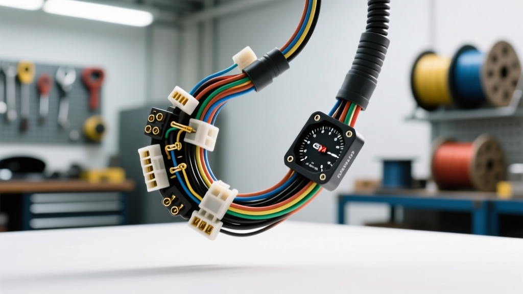
Introduction to Instrument Cluster Wiring Harness Diagnostics
When diagnosing erratic gauge behavior, dead stepper motors, flickering backlights, or total cluster blackouts, the instrument cluster wiring harness is often the true culprit. While many mechanics immediately condemn the instrument cluster PCB or the Body Control Module (BCM), the physical wiring harness and its associated connector pigtails endure severe environmental stress. Behind the dashboard, wiring is subjected to HVAC condensation, extreme thermal cycling from the defroster vents, and mechanical chafing against the steering column bracket.
This comprehensive guide analyzes the true cost of repairing versus replacing an instrument cluster wiring harness, specifically focusing on the notoriously problematic GM GMT800 platform (1999-2006 Silverado, Sierra, Tahoe, and Suburban). We will break down the specialized tool requirements, provide exact wire gauge specifications, and outline a professional diagnostic workflow to ensure your repair lasts the lifetime of the vehicle.
Cost Analysis: OEM Replacement vs. DIY Pigtail Repair
Dealerships and general repair shops often default to replacing the entire forward lamp and dash harness assembly when a localized short or corroded connector is found. This approach is financially devastating for the vehicle owner. Understanding the cost breakdown allows you to make an informed decision between an OEM harness replacement, an aftermarket pigtail adapter, or a precision DIY terminal repair.
| Repair Strategy | Parts Cost | Labor / Time | Total Estimated Cost |
|---|---|---|---|
| Complete OEM Dash Harness | $650 - $950 | 12-16 Hours ($1,500+) | $2,150 - $2,800 |
| Aftermarket Cluster Pigtail | $45 - $85 | 1-2 Hours ($150) | $195 - $285 |
| DIY Terminal & Wire Repair | $35 - $60 | 2-3 Hours (DIY) | $35 - $60 |
| Remanufactured Cluster Unit | $180 - $250 | 1 Hour ($120) | $300 - $370 |
As the table illustrates, replacing the entire harness is rarely necessary unless there is catastrophic melting or widespread rodent damage. In 90% of cluster communication failures, the issue is localized to the 32-pin or 16-pin connector pigtails where automotive terminals suffer from fretting corrosion or locking tang fatigue. Investing in a high-quality aftermarket pigtail or performing a targeted terminal repin saves thousands of dollars and prevents the introduction of new bugs often found in poorly assembled modern replacement harnesses.
Essential Tool Requirements for Harness Repair
Working on modern instrument cluster wiring requires precision. You cannot simply twist wires together and wrap them in electrical tape. The Class 2 Serial Data bus and low-voltage CAN networks require strict adherence to wire geometry and shielding standards to prevent signal degradation and electromagnetic interference (EMI).
Terminal Extraction and Depinning Tools
GM dash harnesses primarily utilize Delphi (now Aptiv) GT 280 and Metri-Pack 280 series connectors. These feature secondary locking mechanisms (TPA - Terminal Position Assurance) and delicate primary locking tangs.
- Terminal Release Tools: A standard flathead screwdriver will destroy the connector housing. You must use a dedicated terminal extraction tool, such as the Lisle 36180 or the OEMTOOLS 25271, which features the precise micro-blade widths required to depress the GT 280 locking tangs without gouging the nylon housing.
- TPA Spudgers: Plastic nylon spudgers are required to safely pop the secondary TPA locks out of the 'pre-lock' position into the 'unlocked' position before terminal extraction can occur.
Wire Stripping, Crimping, and Sealing
The integrity of an instrument cluster harness relies on the crimp profile. Open-barrel F-crimps require specific tooling to achieve the correct compression ratio and pull-out force.
- Ratcheting Crimpers: Use a ratcheting crimper calibrated for Delphi GT 280 terminals (such as the TE Connectivity 58496-1 or Titan 11477). Non-ratcheting pliers will result in cold crimps that vibrate loose under dash resonance.
- Wire Strippers: Precision automatic wire strippers calibrated for 14 to 22 AWG. Stripping too much insulation leaves bare copper exposed to humidity; stripping too little causes the crimp wings to bite into the insulation, creating a high-resistance choke point.
- Adhesive-Lined Heat Shrink: Standard heat shrink is insufficient behind the dash. You must use dual-wall, adhesive-lined heat shrink (such as 3M FP-301). When heated, the inner thermoplastic layer melts and flows into the wire strands, creating a hermetic seal that prevents capillary action from drawing HVAC condensation into the crimp joint.
Testing and Diagnostics
According to Fluke's automotive electrical troubleshooting guidelines, testing data bus lines requires a high-impedance digital multimeter (DMM) or an oscilloscope. A standard test light will overload and potentially fry the BCM's Class 2 data driver. A Fluke 87V is the industry standard for back-probing cluster connectors to verify voltage drops and data bus pulsing.
GM GMT800 Cluster Harness Pinout and Wire Specifications
When repairing the instrument cluster wiring harness on a GMT800 vehicle, you must match the exact AWG and wire color to maintain circuit resistance parameters. The cluster connects via two main connectors: a 32-pin Connector C1 (Power, Ground, Data, Indicators) and a 16-pin Connector C2 (High-speed signals, ABS, 4WD). Below is a critical reference chart for the most commonly repaired circuits on Connector C1.
| Pin | Circuit Function | Wire Color | AWG | Terminal Type |
|---|---|---|---|---|
| A1 | Battery Positive Feed | Orange | 14 | Metri-Pack 280 |
| A2 | Main Ground | Black/White | 14 | Metri-Pack 280 |
| A9 | Class 2 Serial Data | Purple | 20 | GT 280 |
| A10 | Ignition 3 (Run/Start) | Pink | 18 | GT 280 |
| A15 | Instrument Illumination | Brown | 18 | GT 280 |
| B1 | Left Turn Signal Input | Light Blue | 18 | GT 280 |
| B2 | Right Turn Signal Input | Dark Blue | 18 | GT 280 |
| B5 | High Beam Indicator | Green | 18 | GT 280 |
Note: The Class 2 Serial Data line (Pin A9) operates on the SAE J1850 Variable Pulse Width (VPW) standard. As detailed in the SAE J1850 specification, this line pulses between 0V and 7V. Do not splice into this wire with standard T-taps, as the added capacitance will distort the VPW signal and cause communication dropouts across the entire vehicle network.
Step-by-Step Diagnostic and Repair Workflow
If your gauges are dropping to zero intermittently or the 'Service Engine Soon' light is failing to illuminate during the bulb check, follow this professional workflow:
- Isolate the Power Source: Disconnect the negative battery terminal. Wait 5 minutes for the BCM to enter sleep mode to prevent setting ghost U-codes (communication fault codes) when the cluster is unplugged.
- Access the Connectors: Remove the lower steering column shroud and the knee bolster. Reach behind the cluster to depress the locking tabs on the 32-pin and 16-pin connectors.
- Visual Inspection: Inspect the harness routing. A common failure point on the GMT800 is the harness rubbing against the steel steering column support bracket, wearing through the corrugated loom and shorting the 14 AWG Orange battery feed to ground.
- Terminal Drag Test: Using a spare, known-good male terminal, insert it into each female cavity of the cluster connector. If the terminal slides in without a distinct 'click' and drag, the female internal beryllium-copper spring has lost its tension. The terminal must be extracted and replaced.
- Crimp and Seal: Strip the wire using the 20 AWG or 14 AWG setting. Slide the adhesive-lined heat shrink onto the wire before crimping. Perform the F-crimp, tug-test the wire (minimum 15 lbs pull force for 14 AWG), and apply heat until the adhesive seals out the ends.
- Repin and Lock: Insert the new terminal into the housing until it clicks. Push the TPA lock back into its final seated position. Reconnect to the cluster and test.
Common Failure Modes in Dash Harnesses
Beyond physical chafing, the instrument cluster wiring harness suffers from specific chemical and thermal failures. Fretting corrosion is the most prevalent issue. Because the dash experiences micro-vibrations from the engine and road surface, the tin-plated terminals in the GT 280 connectors rub against each other at a microscopic level. This breaks the tin oxide layer, leading to oxidation and high resistance. High resistance on the Pin A2 Ground circuit will cause the stepper motors to behave erratically, as the internal voltage reference shifts.
Another critical failure mode is thermal degradation of the insulation. The 18 AWG Pink Ignition wire and 14 AWG Orange Battery wire run close to the HVAC heater core pipes in some GMT800 configurations. Over a decade of 180°F heat exposure, the cross-linked polyethylene (XLPE) insulation becomes brittle and cracks, exposing bare copper to the grounded metal dash frame. Always use high-temperature automotive primary wire (rated to 125°C, per SAE J1128) when replacing segments of the instrument cluster wiring harness to ensure long-term reliability.