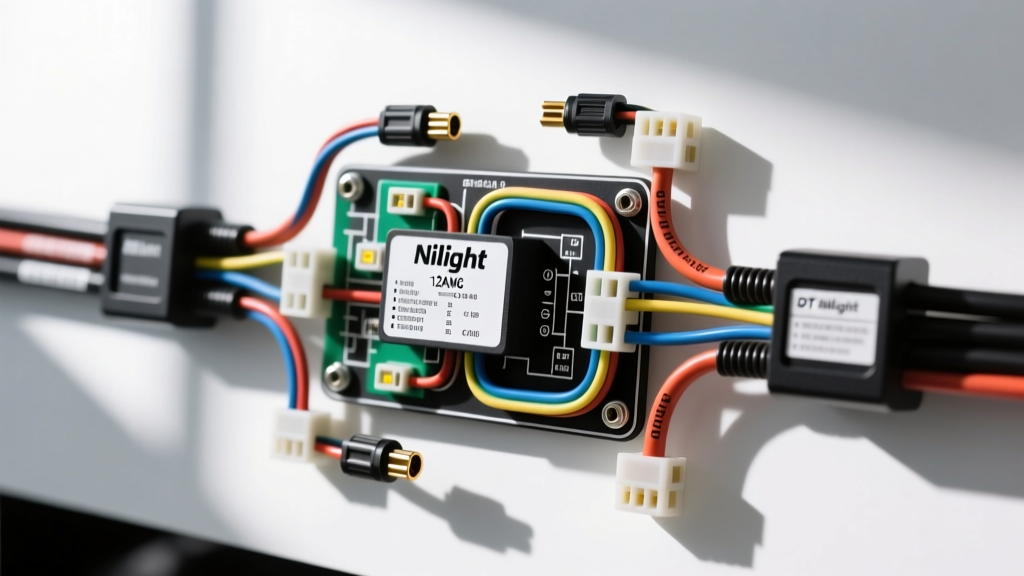
Understanding the Nilight Wiring Harness Diagram
Installing aftermarket LED light bars, pods, or cubes requires more than simply twisting wires together and wrapping them in electrical tape. A proper installation relies on understanding the Nilight wiring harness diagram to ensure safe power delivery, prevent voltage drop, and protect your vehicle's sensitive CAN-bus electrical system from back-feed or short circuits. Nilight harness kits are designed around a standard Bosch-style automotive relay, an inline ATO blade fuse, and weather-sealed Deutsch DT connectors. This practical how-to guide breaks down the exact schematic, wire gauges, and installation steps required for a professional-grade LED lighting setup.
Anatomy of the Nilight Relay Harness Schematic
Before cutting zip ties or routing wires through the firewall, you must understand the components mapped out in the Nilight wiring diagram. The harness acts as an isolated high-current circuit, triggered by a low-current switch. This prevents the high amperage draw of the LEDs from melting your dashboard switch wiring or overloading factory auxiliary circuits.
| Wire Function | Standard Color | AWG Size | Max Amperage (Chassis Wiring) | Insulation Type |
|---|---|---|---|---|
| Main Battery Power (B+) | Red | 14 AWG (or 12 AWG upgrade) | 30A - 40A | PVC / Cross-linked |
| Main Chassis Ground | Black | 14 AWG (or 12 AWG upgrade) | 30A - 40A | PVC / Cross-linked |
| Switch Trigger (+12V) | Yellow / White | 18 AWG | 5A | PVC Primary |
| Relay Coil Ground | Black (Short pigtail) | 18 AWG | 5A | PVC Primary |
| Load to LED (DT Plug) | Red / Black (Duplex) | 14 AWG | 30A | UV-Resistant Jacket |
Bosch-Style Relay Pinout Breakdown
The core of the Nilight wiring harness diagram is the 4-pin or 5-pin ISO mini relay. Most Nilight kits utilize a 4-pin SPST (Single Pole, Single Throw) Normally Open (NO) relay. Here is the exact pin configuration you will see on the relay schematic:
- Pin 30 (Common / Power In): Connects directly to the positive battery terminal via the inline 30A ATO fuse. This is the high-current supply.
- Pin 87 (Normally Open / Load Out): Connects to the positive wire of the Deutsch DT plug, feeding the LED light bar.
- Pin 86 (Coil Trigger +): Connects to the cabin toggle switch. When the switch is pressed, 12V flows here to energize the electromagnetic coil.
- Pin 85 (Coil Ground -): Connects to a clean chassis ground to complete the low-current trigger circuit.
Note: If your kit includes a 5-pin relay, Pin 87a (Normally Closed) will be left empty and capped, as it is only used for alternate switching logic.
Step-by-Step Nilight Harness Installation Guide
Step 1: Battery Preparation and Fuse Placement
Always disconnect the negative battery terminal before beginning any automotive electrical work. According to Littelfuse ATO/ATC specifications, the inline fuse holder must be positioned as close to the power source as possible—ideally within 6 to 8 inches of the battery positive post. This ensures that if the main 14 AWG red wire chafes against the chassis before reaching the relay, the fuse will blow immediately, preventing a thermal event.
Use a marine-grade, heat-shrink ring terminal (12-10 AWG to 1/4 inch stud) for the battery connection. Torque the battery terminal nut to the vehicle manufacturer's specification, typically between 5-7 Nm (45-60 in-lbs), to prevent micro-arcing under high-vibration off-road conditions.
Step 2: Routing the 12 AWG / 14 AWG Main Power
While standard Nilight diagrams show 14 AWG wire, SAE J1128 standards for low-tension primary cable dictate that wire gauge must be selected based on length and amperage to prevent voltage drop. If you are running a 300W+ LED bar (drawing 25+ amps) and the routing distance from battery to light bar exceeds 15 feet (round trip), upgrade the main red and black wires to 12 AWG.
Route the harness along the factory wiring loom in the engine bay. Avoid exhaust manifolds, turbocharger downpipes, and steering shafts. Secure the harness every 12 inches using UV-resistant nylon zip ties or Tesa 51036 PET cloth tape to prevent abrasion against the aluminum radiator core support.
Step 3: Firewall Pass-Through for the Toggle Switch
The 18 AWG switch trigger wire must pass from the engine bay into the cabin. Never pierce the rubber weather seal of an existing factory grommet with a sharp tool. Instead, locate a blank rubber grommet on the firewall, remove it, and drill a small 3/16-inch hole in the center. Feed the switch wire through, apply a dab of dielectric grease to the wire, and reinstall the grommet. This maintains the cabin's IP67 weather seal and prevents carbon monoxide or water intrusion.
Step 4: Terminating the Deutsch DT Connectors
Nilight utilizes Deutsch DT series connectors for the final connection to the LED pods or bars. These connectors provide an IP68 waterproof seal, but only if assembled correctly:
- Strip 5/16 inch of insulation from the 14 AWG load wires.
- Crimp the solid DT pins using a specialized open-barrel crimping tool (do not use standard insulated terminal crimpers).
- Insert the pins into the DT plug housing until you hear an audible click, confirming the retention tang has locked.
- Critical Step: Insert the orange plastic wedge lock into the front of the connector. This forces the pins apart slightly, ensuring a tight mating connection and preventing them from backing out under vibration.
- Apply a thin layer of silicone dielectric grease to the silicone seal before mating the plug to the LED bar receptacle.
Calculating Voltage Drop for Long Harness Runs
A common failure mode when following basic wiring diagrams is ignoring voltage drop. LEDs require a minimum of 11.5V to operate at full lumens. If your Nilight harness is routed 20 feet to a roof rack, the resistance of 14 AWG copper wire will cause a voltage drop.
Formula: Voltage Drop = (2 x Length x Current x Wire Resistance per foot)
For a 25A light bar using 14 AWG wire (0.00252 ohms/ft) over a 20-foot one-way run:
Drop = 2 x 20 x 25 x 0.00252 = 2.52 Volts.
Subtracting 2.52V from a 12.6V charging system leaves only 10.08V at the light bar, resulting in dim output and potential flickering. In this scenario, the diagram must be adapted to use 10 AWG or 12 AWG wire for the main power and ground runs.
Troubleshooting Common Nilight Harness Failures
If your LED setup is not functioning after following the diagram, use this diagnostic matrix to identify the fault:
- Symptom: Relay clicks rapidly, but lights do not turn on.
Cause: Severe voltage drop or a short circuit in the DT connector causing the inline 30A fuse to blow or the battery voltage to collapse.
Fix: Check the ATO fuse. Inspect the DT plug for pinched wires or missing wedge locks causing a dead short between Pin 1 and Pin 2. - Symptom: Lights turn on, but the toggle switch gets hot to the touch.
Cause: The switch is wired on the high-current load side instead of the low-current trigger side (Pin 86).
Fix: Rewire the switch to only carry the 0.2A relay coil trigger current, not the 25A LED load. - Symptom: Lights flicker when hitting bumps.
Cause: Loose chassis ground or corroded battery ring terminal.
Fix: Remove the ground ring terminal, sand the chassis paint down to bare metal using 80-grit sandpaper, reattach, torque to spec, and coat with liquid electrical tape to prevent galvanic corrosion. - Symptom: LEDs stay on even when the switch is off.
Cause: Back-feed from a CAN-bus system if the trigger wire was tapped into a factory lighting circuit instead of a dedicated switched 12V source.
Fix: Install a 1N4007 blocking diode on the 18 AWG trigger wire to prevent reverse polarity voltage bleed, or use an Add-A-Fuse on an ignition-switched accessory circuit.
Final Inspection and Testing
Once the Nilight wiring harness diagram has been fully executed, reconnect the battery negative terminal. Turn on the cabin toggle switch and verify the relay engages with a solid, single click. Use a digital multimeter set to DC Voltage to probe the back of the Deutsch connector; you should read within 0.2V of the battery's resting voltage. Finally, secure all remaining slack with split-loom tubing and zip ties, ensuring the relay is mounted vertically with the pins facing downward to prevent water pooling inside the connector housing.