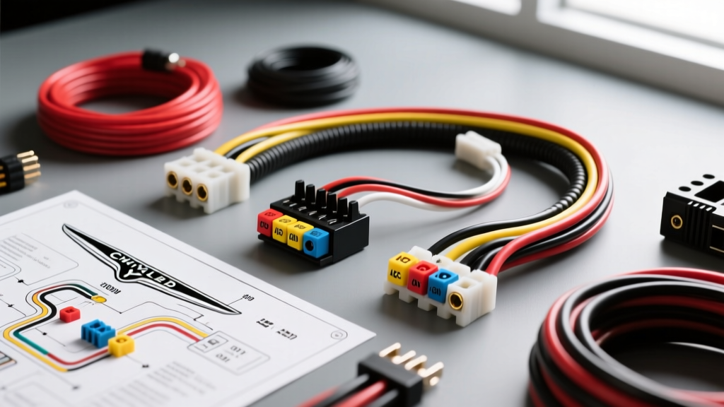
Understanding the Chrysler 300C Audio Architecture
Upgrading the stereo in a Chrysler 300C (specifically the highly popular 2005-2010 LX platform generation) is a rewarding project, but it requires more than just matching wire colors. Unlike older vehicles that relied on simple 12-volt accessory triggers, the 300C utilizes a multiplexed CAN-bus (Controller Area Network) data system. This means the factory radio receives its 'wake-up' signal via digital data rather than a traditional ignition wire. For beginners, understanding this fundamental difference is the key to a successful installation. This guide breaks down the Chrysler 300C radio wiring diagram into digestible, beginner-friendly concepts while providing the exact technical specifications you need to get the job done right.
The CAN-Bus Hurdle: Why Your New Radio Won't Turn On
The most common mistake beginners make when consulting a standard Chrysler 300C radio wiring diagram is looking for a red 'accessory' or 'ignition' wire. In the LX platform, the Totally Integrated Power Module (TIPM) manages power distribution, and the radio is commanded to turn on via the CAN-bus network. If you simply wire an aftermarket head unit's red ignition wire to a fused 12V source, you risk draining your battery or triggering a TIPM fault code. To solve this, you must use a CAN-bus interface module (such as the PAC C2R-CHY4 or the iDatalink Maestro RR). These modules listen to the vehicle's data network and generate a traditional 12V accessory output for your aftermarket stereo, bridging the gap between modern digital networks and legacy analog audio equipment.
Essential Tools for Your First Stereo Install
Before pulling any trim panels, ensure you have the proper tools. Working with automotive electrical systems requires precision to prevent short circuits and voltage drops.
- Wire Strippers & Crimpers: Capable of handling 18 AWG to 12 AWG wire.
- Heat Shrink Tubing & Heat Gun: Never use electrical tape for permanent in-dash connections; it unravels in summer heat.
- Digital Multimeter: Essential for verifying constant 12V, ground continuity, and CAN-bus voltage (typically 2.5V to 3.5V).
- Trim Removal Tools: Nylon pry tools to prevent marring the 300C's soft-touch dash materials.
- Panel Clip Assortment: Chrysler door and dash clips are notoriously brittle on older LX vehicles.
Decoding the Chrysler 300C Radio Wiring Diagram
The standard base-model Chrysler 300C utilizes a 22-pin main harness connector (C1). Below is the foundational pinout table for the standard audio system. Always verify these colors with a multimeter, as mid-year production changes and previous owner modifications can alter the wiring.
| Pin Number | Wire Color | Function / Description |
|---|---|---|
| 1 | Red / White | Fused Battery (+) - Constant 12V Memory |
| 2 | Black / Light Green | Chassis Ground (-) |
| 3 | Pink / White | Fused Ignition (Run/Start) - *Note: Often inactive on CAN-bus trims* |
| 7 | White / Dark Green | CAN-Bus High (Data +) |
| 8 | White / Light Green | CAN-Bus Low (Data -) |
| 11 | Dark Green | Left Front Speaker (+) |
| 12 | Dark Green / White | Left Front Speaker (-) |
| 13 | Violet | Right Front Speaker (+) |
| 14 | Violet / White | Right Front Speaker (-) |
| 15 | Brown | Left Rear Speaker (+) |
| 16 | Brown / White | Left Rear Speaker (-) |
| 17 | Dark Blue | Right Rear Speaker (+) |
| 18 | Dark Blue / White | Right Rear Speaker (-) |
Source reference: Wiring schematics align with Chrysler Tech Authority factory service manual standards for the LX platform.
Handling the Premium Boston Acoustics / MyGIG System
If your 300C Touring or Signature edition is equipped with the premium Boston Acoustics or Alpine amplifier system, the wiring diagram changes significantly. The factory head unit outputs low-level (pre-amp) signals to an external amplifier located in the trunk on the driver's side. Furthermore, the front door speakers are wired in a multi-way component setup (separate tweeters and woofers) managed by the factory amp's internal crossover.
Option A: The Amplifier Bypass (Budget-Friendly)
If you are installing a high-power aftermarket head unit (4x50W RMS) and new aftermarket speakers, you can bypass the factory amplifier entirely. This requires running new 16 AWG speaker wire from the dash harness directly to each door speaker, bypassing the trunk amp and factory door crossovers. While labor-intensive, this guarantees clean, unfiltered full-range audio to your new components.
Option B: Retaining the Factory Amp (OEM Integration)
To keep the factory amplifier, you must use a specialized CAN-bus interface with RCA pre-amp outputs (like the PAC RP4-CH11 or Maestro RR). The interface converts the digital CAN-bus wake-up command into a 12V remote turn-on lead for the factory amp, while your aftermarket radio's RCA outputs feed the amp's low-level inputs. According to automotive electrical best practices outlined by Crutchfield's Car Audio Wiring Guide, ensuring proper RCA shielding is vital here to prevent the infamous 'alternator whine' common in high-current Chrysler charging systems.
Step-by-Step Beginner Wiring Workflow
- Disconnect the Battery: Always disconnect the negative battery terminal and wait 10 minutes. This prevents accidental airbag deployment and stops the TIPM from logging soft-codes when the radio loses power.
- Trim Removal: Carefully pry off the silver dash bezel surrounding the climate controls and radio. Remove the four 7mm hex screws securing the factory radio bracket.
- Interface Preparation: Connect your CAN-bus interface module to the vehicle's 22-pin harness. Solder and heat-shrink all connections. Do not use twist-connectors.
- Bench Test: Before pushing the radio into the dash, reconnect the battery temporarily and turn on the ignition. Verify that the aftermarket radio powers on, the CAN-bus module retains memory, and all four speaker channels produce sound.
- Final Assembly: Tuck the interface module and excess wiring deep into the HVAC cavity behind the radio to prevent rattling against the chassis.
Common Troubleshooting Scenarios
Symptom: Radio Turns On, But No Sound
Cause: The factory amplifier is not waking up.
Fix: Check the blue/white 'Remote Turn-On' wire from your aftermarket radio or interface module. Use a multimeter to ensure it is outputting 12V when the key is in the 'ON' position. If using a Maestro module, verify the firmware was flashed with the 'Retain Factory Amp' box checked.
Symptom: Loud 'Pop' From Speakers When Turning Off Car
Cause: The amplifier is shutting down before the radio's audio signal stops, causing a voltage spike.
Fix: Install a 1000µF capacitor or a delay relay on the remote turn-on lead to keep the amplifier awake for 2-3 seconds after the ignition is turned off.
Symptom: Steering Wheel Controls Not Functioning
Cause: Missing CAN-bus data translation.
Fix: Standard resistive SWC interfaces will not work on the 300C. You must use a data-driven SWC module (like the PAC SWI-CP5) that reads the steering wheel button presses directly from the CAN-bus network and translates them into IR or resistive signals for your aftermarket head unit.
Final Thoughts on Wire Gauge and Safety
When expanding your system beyond the head unit, respect the physics of electrical current. If you are adding an aftermarket subwoofer amplifier, run a minimum of 8 AWG OFC (Oxygen-Free Copper) power wire directly from the positive battery terminal, utilizing an inline ANL fuse within 18 inches of the battery. The Chrysler 300C's charging system is robust, but voltage drops across undersized CCA (Copper-Clad Aluminum) wire will starve your amplifier and cause clipping, which destroys speakers faster than over-powering them. By respecting the vehicle's CAN-bus architecture and adhering to proper wiring fundamentals, your 300C audio upgrade will be reliable, safe, and sonically superior.