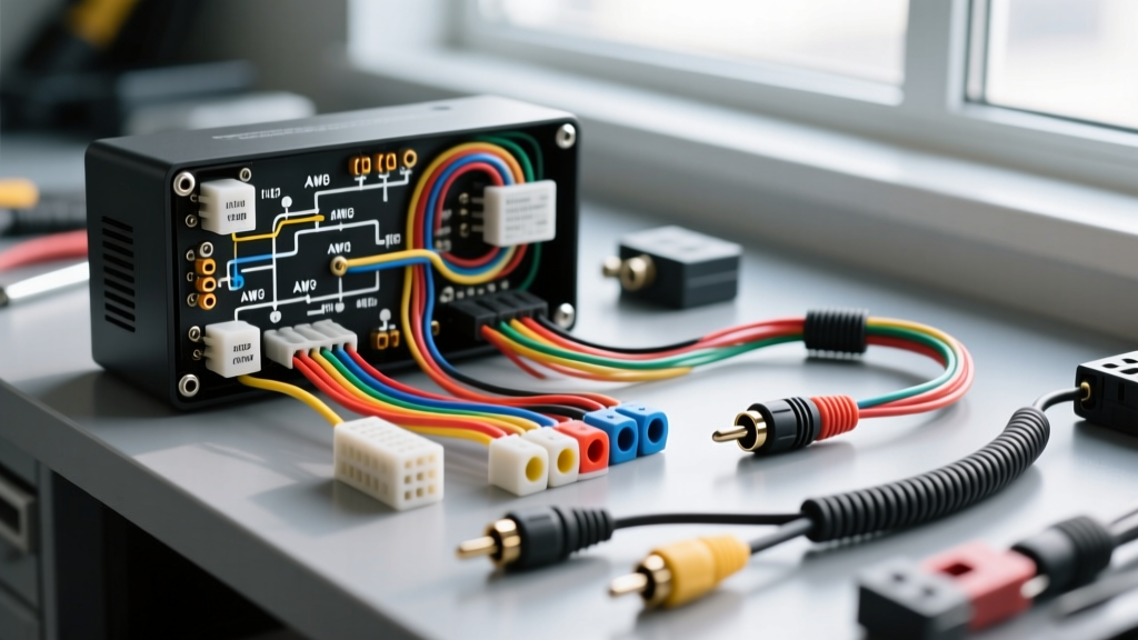
Architecting the Complete Car Audio System Wiring Diagram
Installing a high-fidelity aftermarket stereo requires far more than simply connecting red to red and black to black. A complete car audio system wiring diagram serves as the master blueprint for managing high-current 12V DC power, low-voltage analog audio signals, and digital communication buses. Whether you are running a 1000W RMS subwoofer amplifier, a 4-channel Class D amp for component speakers, or integrating a digital signal processor (DSP), understanding the physical layer of your electrical system is critical. This walkthrough dissects the anatomy of a professional-grade car audio wiring harness, referencing SAE J1128 low-tension cable standards and Crutchfield's master wiring guides to ensure your installation is safe, noise-free, and optimized for peak acoustic output.
Phase 1: High-Current Power and Ground Distribution
The foundation of any car audio system wiring diagram is the power delivery network. Amplifiers demand massive transient current bursts, especially during low-frequency bass transients. If the wiring is undersized, the amplifier's internal voltage rails will sag, triggering protection modes or introducing severe clipping.
Selecting the Correct AWG and Conductor Material
Always specify Oxygen-Free Copper (OFC) over Copper-Clad Aluminum (CCA). CCA wire has approximately 40% higher electrical resistance than OFC, which leads to excessive voltage drop and heat generation. According to AutoShop 101's automotive electrical curriculum, maintaining a voltage drop of less than 0.5V at peak current draw is essential for amplifier longevity.
| AWG Size | Max Current (Amps) | Typical Application | Terminal Torque Spec |
|---|---|---|---|
| 1/0 AWG | 350A+ | Multi-amp systems, competition SPL builds | 4.5 - 6.0 Nm |
| 4 AWG | 150A - 200A | 1000W - 1500W RMS Mono Subwoofer Amp | 2.5 - 3.5 Nm |
| 8 AWG | 80A - 100A | 4-Channel Amp (600W RMS total) or DSP | 1.5 - 2.0 Nm |
| 12 AWG | 40A - 50A | Compact Class D Amps, Active Crossovers | 0.8 - 1.2 Nm |
The Main Fuse and Distribution Block
Your wiring diagram must include an ANL or Class-T fuse located within 18 inches of the positive battery terminal. This protects the vehicle from a catastrophic short circuit in the event the main power wire chafes against the chassis. From the fuse, the 4 AWG main power wire should route through the firewall using a rubber grommet, terminating at a fused distribution block. The ground wire must be exactly the same AWG and length as the power wire, terminating to a sanded, bare-steel chassis point secured with a stainless steel hex bolt and treated with anti-corrosion dielectric gel.
Phase 2: Signal Routing and EMI Mitigation
The most common failure in DIY car audio system wiring is alternator whine—a high-pitched noise that rises and falls with engine RPM. This is caused by Electromagnetic Interference (EMI) inducing alternating current noise into the low-voltage RCA signal cables.
RCA Routing Rules
To prevent EMI, your wiring diagram must physically separate high-current DC power cables from low-voltage analog signal cables. Route the 4 AWG power wire and RCA cables on opposite sides of the vehicle's center console. If they must cross, ensure they intersect at a strict 90-degree angle to minimize the surface area for inductive coupling. Always use shielded, twisted-pair RCA cables; the twisting cancels out common-mode noise, while the braided shield drains induced RF interference to the chassis ground.
Phase 3: The Remote Turn-On Circuit and Relay Integration
The remote turn-on wire (typically 18 AWG Blue/White) signals the amplifier to power up when the head unit is active. However, the internal transistor switching the remote output on most aftermarket head units is only rated for 200mA to 300mA. If you are wiring multiple amplifiers, a DSP, and a line driver, the cumulative current draw can exceed this limit, frying the head unit's internal logic board.
Integrating a Bosch-Style 12V Relay
For high-current remote circuits, insert a standard 40A SPST automotive relay into your wiring diagram. This isolates the head unit's delicate circuitry from the heavy inductive load of the amplifier power supplies.
- Pin 86 (Coil +): Connect to the head unit's Blue/White remote output (18 AWG).
- Pin 85 (Coil -): Connect to a clean chassis ground (18 AWG).
- Pin 30 (Common): Connect directly to the 12V+ battery terminal or distribution block via an inline 5A fuse (12 AWG).
- Pin 87 (Normally Open): Connect to the remote turn-on terminals of all amplifiers and DSPs (14 AWG).
When the head unit sends 12V to Pin 86, the electromagnetic coil pulls the internal contactor, bridging Pin 30 to Pin 87, and delivering robust, high-current 12V to your audio rack without stressing the stereo.
Phase 4: Speaker Wire Routing and EIA Color Codes
Standardizing your speaker wire colors prevents phase cancellation and ensures accurate stereo imaging. The Consumer Technology Association (CTA), formerly the CEA, established the EIA RS-770 standard for aftermarket car audio wiring colors. Adhering to this standard ensures that any technician can troubleshoot your system years down the road.
| Channel | Positive (+) Wire Color | Negative (-) Wire Color | Recommended AWG |
|---|---|---|---|
| Front Left | White | White w/ Black Stripe | 16 AWG OFC |
| Front Right | Grey | Grey w/ Black Stripe | 16 AWG OFC |
| Rear Left | Green | Green w/ Black Stripe | 16 AWG OFC |
| Rear Right | Purple | Purple w/ Black Stripe | 16 AWG OFC |
| Subwoofer 1 | Blue | Blue w/ Black Stripe | 12 AWG OFC |
| Subwoofer 2 | Brown | Brown w/ Black Stripe | 12 AWG OFC |
Impedance Matching and Subwoofer Wiring
When wiring Dual Voice Coil (DVC) subwoofers, your diagram must reflect the target impedance of the amplifier. A Class D mono amplifier typically operates most efficiently and safely at a 2-ohm or 1-ohm final load. For example, wiring two DVC 4-ohm subwoofers in parallel yields a 1-ohm load, while wiring them in series yields a 4-ohm load. Always use a digital multimeter to verify the final impedance at the amplifier's speaker terminals before applying power. A reading significantly lower than the amplifier's rated minimum will trigger thermal or over-current protection immediately.
Troubleshooting Common Wiring Faults
Even with a perfect car audio system wiring diagram, physical installation errors occur. Use this decision tree to diagnose common faults:
- Symptom: Amplifier Protection Light (Red) Illuminates Immediately.
Cause: Shorted speaker wire touching the chassis, or final subwoofer impedance below the amp's minimum threshold.
Fix: Disconnect all speaker wires. Power on the amp. If it stays on, the fault is in the speaker wiring. Check for pinched 16 AWG wires behind door panels. - Symptom: Severe Alternator Whine in the Audio Signal.
Cause: Ground loop. The head unit and amplifier are referencing different ground potentials, causing current to flow through the RCA shields.
Fix: Verify the amplifier ground is sanded to bare metal. Ensure the head unit ground (Black wire) is tied to a thick, factory chassis bolt, not a thin dash bracket. - Symptom: Amplifier Clipping at Moderate Volumes.
Cause: Voltage drop on the main power wire due to undersized AWG or a blown main fuse strand.
Fix: Measure DC voltage at the amp's B+ and GND terminals while playing bass-heavy test tones at 50Hz. If voltage drops below 11.5V, upgrade from 8 AWG to 4 AWG power wire and check battery alternator output.
Final Verification and System Commissioning
Before reconnecting the vehicle's negative battery terminal, perform a final visual inspection of every connection. Ensure all hex crimps are secured with marine-grade adhesive heat shrink to prevent moisture ingress and copper oxidation. Set all amplifier gains to their minimum detent, verify the DSP crossover slopes, and use an oscilloscope or a digital multimeter with an AC millivolt adapter to set your gain structure properly. By strictly following this complete car audio system wiring walkthrough, you guarantee a reliable, high-output audio system that will perform flawlessly for the life of the vehicle.