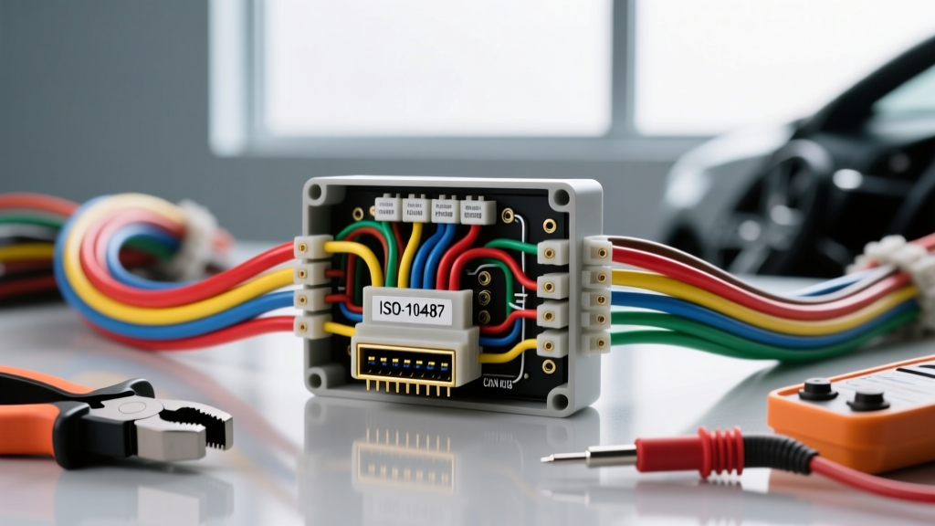
The Anatomy of the ISO 10487 Standard
Introduced to standardize the chaotic landscape of factory automotive radio wiring, the ISO 10487:2012 Standard defines the physical dimensions, pin configurations, and electrical characteristics for car audio connectors. For automotive electrical technicians and advanced DIY installers, understanding the car audio ISO connector goes far beyond simply plugging in a harness adapter. It requires a deep comprehension of current limits, manufacturer-specific anomalies, and modern data-bus integration.
The standard ISO harness is divided into distinct blocks, universally color-coded to prevent cross-mating. The two primary blocks utilized in almost every aftermarket head unit installation are Block A (Power and Control) and Block B (Speaker Outputs). While newer vehicles utilize proprietary connectors like Quadlock or Fakra, the ISO standard remains the foundational bridge between the vehicle's chassis wiring and the aftermarket stereo's internal circuitry.
Block A: Power and Control Signals (Pins 1-8)
Block A handles the low-frequency, high-current power delivery and auxiliary control signals. The standard wire gauge for Block A power circuits is 18 AWG (0.82 mm²), while control wires are typically 20 AWG (0.5 mm²).
- Pin 1 (Speed Pulse): Often used in European vehicles to feed a vehicle speed signal (VSS) to the head unit for speed-sensitive volume control. Outputs a square wave proportional to wheel speed.
- Pin 2 (Mute / Telephone): A logic-level trigger used to mute the audio output when an OEM Bluetooth module or cellular phone receives a call. Usually active-low.
- Pin 3 (Reserved): Unpopulated in standard configurations; occasionally used for proprietary OEM diagnostic lines.
- Pin 4 (+12V Permanent / Battery): Yellow wire. Provides continuous 12V DC directly from the battery to maintain the head unit's volatile memory (presets, clock). Must be fused.
- Pin 5 (Antenna Trigger): Blue wire. Outputs +12V when the radio is turned on or switched to the AM/FM tuner, triggering a power antenna motor or an external amplifier's remote turn-on lead.
- Pin 6 (Illumination): Orange wire. Receives a variable or switched 12V signal from the vehicle's dashboard dimmer circuit to adjust the head unit's display brightness.
- Pin 7 (+12V Switched / Accessory): Red wire. Receives 12V only when the ignition is in the 'ACC' or 'ON' position. This signals the head unit's internal power supply to wake up.
- Pin 8 (Ground): Black wire. The primary chassis ground return path for both Block A and Block B circuits.
Block B: Speaker Outputs (Pins 1-8)
Block B is dedicated exclusively to amplified speaker-level outputs. The standard utilizes a universally recognized color-coding system with solid colors for positive (+) and striped colors for negative (-) terminals.
- Pins 1 & 2 (Front Left): White (+) / White with Black Stripe (-)
- Pins 3 & 4 (Front Right): Gray (+) / Gray with Black Stripe (-)
- Pins 5 & 6 (Rear Left): Green (+) / Green with Black Stripe (-)
- Pins 7 & 8 (Rear Right): Purple (+) / Purple with Black Stripe (-)
Expert Warning: Never ground any Block B negative speaker wire to the vehicle chassis. Modern aftermarket head units utilize BTL (Bridge-Tied Load) amplifier topologies. Grounding a negative speaker wire will short the internal IC, instantly destroying the output channel and potentially causing a thermal fire.
Manufacturer-Specific Anomalies: The VAG Pin Swap
While the ISO 10487 standard dictates that Pin 4 is Permanent 12V and Pin 7 is Switched 12V, several major automakers deliberately invert this logic. The most notorious offenders are the Volkswagen Audi Group (VAG) and the PSA Group (Peugeot/Citroën). As detailed in the Crutchfield VW Stereo Installation Guide, these vehicles supply Switched 12V to Pin 4 and Permanent 12V to Pin 7.
| Pin Number | Standard ISO 10487 | VAG / PSA OEM Configuration | Consequence of Mismatch |
|---|---|---|---|
| Pin 4 | +12V Permanent (Memory) | +12V Switched (Ignition) | Radio loses memory/presets every time the car is turned off. |
| Pin 7 | +12V Switched (Ignition) | +12V Permanent (Battery) | Radio remains on indefinitely, causing severe parasitic battery drain. |
The Fix: You must physically extract the brass terminals from Pins 4 and 7 on the vehicle-side ISO adapter harness and swap their positions in the plastic housing. Use a precision terminal extraction tool or a small jeweler's screwdriver to depress the locking tang on the Molex-style terminal. Never cut and splice these wires behind the connector if it can be avoided, as adding resistance to the primary power delivery circuit exacerbates voltage drop.
Current Limitations and High-Draw Amplifier Bypasses
A critical, often overlooked failure mode in car audio installation is the thermal limit of the ISO connector itself. The standard brass terminals inside an ISO Block A housing are typically rated for a maximum continuous current of 10 Amps. The 18 AWG wire used in standard harnesses is rated for roughly 14 Amps in free air, but less when bundled in a tight dashboard cavity.
If you are installing a high-powered aftermarket head unit (e.g., 22W x 4 RMS internal amplification) or using the ISO harness to pass power to a compact Class D subwoofer amplifier, peak current draw can easily exceed 15 Amps. Pushing 15A through a 10A-rated ISO terminal causes localized resistance, leading to a severe voltage drop at the head unit and thermal deformation of the PBT (polybutylene terephthalate) plastic connector housing.
Upgrading the Power Delivery Circuit
To safely support high-current draws while maintaining the ISO standard for speaker and control signals, perform a power bypass:
- Extract Pins: Remove the Pin 4 (Yellow) and Pin 8 (Black) terminals from the aftermarket head unit's ISO Block A harness.
- Solder and Seal: Solder a length of 12 AWG (3.31 mm²) primary automotive wire to the extracted terminals. Seal the connections with dual-wall adhesive-lined heat shrink.
- Direct Routing: Route the 12 AWG Yellow wire directly to the vehicle's battery positive terminal, passing through the firewall via a grommet. Install a 15A ATC inline fuse within 18 inches of the battery.
- Chassis Ground: Route the 12 AWG Black wire to a verified, bare-metal chassis ground point. Scrape away all paint and clear coat, secure with an M6 or M8 ring terminal, and apply dielectric grease to prevent oxidation.
- Isolate the Harness: Clip and tape off the original Pin 4 and Pin 8 wires in the vehicle-side ISO harness to prevent back-feeding current through the factory wiring loom.
CAN-Bus and Data Line Integration (Block C & Beyond)
In modern vehicles (roughly 2005 and newer), the traditional 12V Switched Accessory wire (Pin 7) has been largely eliminated to reduce copper weight and parasitic draw. Instead, the vehicle utilizes a Controller Area Network (CAN-bus) to send digital wake-up packets to the infotainment module.
When installing an aftermarket stereo in a CAN-bus vehicle, the ISO Block A Pin 7 will read 0V, even with the ignition on. If connected directly, the aftermarket radio will never turn on. To resolve this, installers must use a CAN-bus to ISO interface module (such as those from PAC, Axxess, or Connects2). These modules tap into the vehicle's CAN-High and CAN-Low twisted pair data lines, interpret the digital 'Ignition ON' hex packet, and trigger an internal solid-state relay to supply a simulated +12V switched output to the ISO Block A Pin 7.
Troubleshooting Common ISO Harness Failures
Reference this diagnostic matrix when encountering electrical faults during or after an ISO-based stereo installation. For foundational electrical testing procedures, consult the AutoShop 101 Automotive Electrical Manual.
| Symptom | Probable Cause | Diagnostic & Repair Action |
|---|---|---|
| Head unit powers on but shuts off immediately when volume is increased. | Severe voltage drop on Pin 4 or Pin 8 due to undersized wire or poor ground. | Measure voltage at the back of the ISO connector under load. If it drops below 11.5V, perform the 12 AWG power bypass outlined above. |
| Alternator whine (high-pitched noise) that increases with engine RPM. | Ground loop caused by sharing a ground point with fuel pumps or ignition coils, or Pin 8 resistance. | Relocate the ISO Block A Pin 8 ground to a dedicated, clean chassis point. Verify RCA cables are routed on the opposite side of the vehicle from power wires. |
| Radio turns on, but no audio from speakers; head unit displays 'Error' or 'Protect'. | Shorted speaker wire in Block B, or OEM amplified system (e.g., Bose/Harman Kardon) mismatch. | Disconnect Block B. Use a multimeter to check continuity between each speaker pin and chassis ground. If OEM amplified, use a line-out converter (LOC) rather than direct ISO speaker outputs. |
| Head unit turns on with ignition but resets stations/clock every time the car is turned off. | VAG/PSA Pin Swap issue, or Pin 4 is connected to a switched fuse box circuit instead of constant 12V. | Verify constant 12V on Pin 4 with the key removed. If absent, swap Pin 4 and Pin 7 terminals in the ISO housing. |
Final Verification and Safety Protocols
Before pushing the ISO connectors fully into the back of the head unit and securing the chassis into the dash, always perform a 'bench test'. Connect the ISO harness with the radio resting on a microfiber towel outside the dash cavity. Verify memory retention, accessory wake-up, illumination dimming, and all four speaker channels. Only after confirming flawless electrical logic should you route the wiring, apply Tesa cloth tape to prevent dash rattles, and lock the unit into the DIN sleeve. Precision in ISO wiring separates professional integrators from amateur installers.