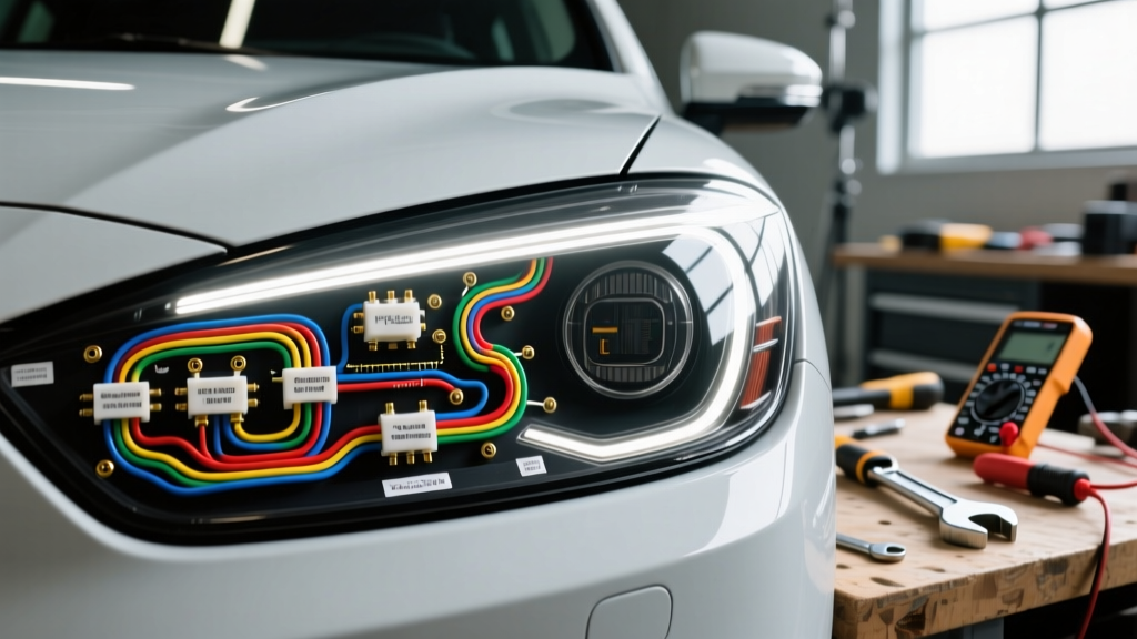
Integrating Car Audio Triggers Using a Headlamp Wiring Diagram
Modern car audio installations extend far beyond simple speaker swaps. Integrating high-channel-count Digital Signal Processors (DSPs), multi-amplifier systems, and aftermarket head units requires precise access to switched 12V+ (Accessory) and illumination (Dimmer) circuits. In late-model vehicles, accessing these signals directly from the lighting harness without consulting a factory headlamp wiring diagram is a recipe for catastrophic Body Control Module (BCM) failure. This practical guide explains how to interpret OEM lighting schematics to safely isolate and tap these circuits for car audio triggers, preventing CAN-bus errors and protecting sensitive automotive computers.
The Evolution of Headlamp Circuits in Modern Vehicles
Historically, a headlamp switch was a simple high-current mechanical device that routed raw 12V+ directly to the bulbs and the dash illumination circuit. Car audio installers could easily tap the brown or orange illumination wire behind the switch to trigger an aftermarket radio's dimmer function. Today, that approach is obsolete and dangerous.
Modern vehicles utilize multiplexed networks. The physical headlamp switch is often just a low-current input device sending a 5V logic signal, a resistor-ladder voltage drop, or a LIN-bus (Local Interconnect Network) message to the BCM or Steering Column Control Module (SCCM). The BCM then processes this request and uses high-side or low-side solid-state drivers to power the lamps, frequently utilizing Pulse Width Modulation (PWM) for dash dimming. Tapping a 5V logic line or a PWM dimming circuit directly into an aftermarket stereo's 12V trigger wire will result in violent screen strobing, erratic amplifier turn-on, or a fried BCM logic board.
Table 1: Common Headlamp Switch Signal Types
| Circuit Type | Voltage / Signal | Audio Tap Compatibility | Required Interface |
|---|---|---|---|
| Raw 12V+ (Pre-2005) | 12V - 14.4V DC | Direct Tap Safe | POSI-TAP / Solder |
| 5V Logic / Resistor Ladder | 1.5V - 5V DC | Unsafe (Will fry radio) | 12V Isolation Relay |
| LIN-Bus / Multiplex | Digital Square Wave | Unsafe (Will crash network) | CAN-bus Interface Module |
| PWM Dimming Output | 12V Pulsed (100Hz+) | Unsafe (Causes strobing) | Relay or PWM Filter |
Step-by-Step Guide: Tapping the Headlamp Circuit Safely
To safely derive a switched 12V+ trigger and a steady illumination signal for your DSP and amplifiers, you must use the headlamp wiring diagram to locate the input request side of the BCM, and use an isolation relay to generate your own clean 12V+ audio trigger. You can access OEM diagrams via professional services like Mitchell1 ProDemand or factory service manuals.
Step 1: Identify the Request Wire via the Diagram
Locate the headlamp switch connector on your diagram. Look for the wire labeled 'Headlamp Switch Signal', 'Park Lamp Request', or 'Headlamp ON Request'. Note the connector cavity number (e.g., Connector X2, Pin 4) and the wire color. Never trust wire color alone; always verify the cavity pinout against the specific model year's diagram, as mid-year production changes frequently alter harness colors.
Step 2: Verify the Signal with a High-Impedance DMM
Do not use a standard incandescent test light. A test light draws current and can instantly destroy a low-current BCM logic driver. Use a high-impedance Digital Multimeter (DMM) or a dedicated automotive logic probe. Back-probe the identified pin. If you see a steady 5V or 12V when the headlamps are turned ON, and 0V when OFF, you have found a safe trigger point. If you see a rapidly fluctuating voltage (PWM) or a square wave, you are on an output or data bus and must find an alternative circuit.
Step 3: Install a Bosch ISO Isolation Relay
To protect the vehicle's multiplexed network from the inductive kickback of your audio equipment and to provide adequate current for multiple amp turn-on leads, wire a standard 4-pin ISO mini relay. According to The12Volt relay logic standards, the pinout is as follows:
- Pin 86: Connect to the verified headlamp request wire (using a POSI-TAP to avoid cutting the OEM harness).
- Pin 85: Connect to a clean, bare-metal chassis ground. Crucial: If the BCM uses a low-side driver (switching the ground side), Pin 86 goes to a fused 12V+ constant, and Pin 85 goes to the BCM headlamp request wire.
- Pin 30: Connect to a fused 12V+ constant battery source (use an inline 5A ATO fuse).
- Pin 87: This is your new, clean 12V+ switched output. Route this to your DSP's 'REM IN', your amplifiers' 'REM' terminals, and your head unit's 'ILL' (Illumination) wire.
Step 4: The Flyback Diode Protection (Expert Requirement)
When the relay coil de-energizes, it generates a reverse voltage spike (inductive kickback) that can exceed 50V. In older cars, this spike dissipates harmlessly. In modern cars with solid-state BCM drivers, this spike can punch through the BCM's internal transistor, resulting in a $1,200+ module replacement. Solder a 1N4001 rectifier diode across Pins 85 and 86 of the relay, with the diode's cathode (silver stripe) facing the positive side. This clamps the voltage spike and protects the vehicle's CAN-bus architecture, adhering to SAE J1113 Electromagnetic Compatibility guidelines for transient emissions.
Wire Gauge and Routing Specifications
Proper wire sizing ensures your amplifiers turn on simultaneously without voltage sag, while keeping the trigger circuit immune to alternator whine and EMI (Electromagnetic Interference).
Table 2: Audio Trigger & Illumination Wiring Specs
| Circuit Segment | Recommended AWG | Wire Type | Max Run Length |
|---|---|---|---|
| BCM to Relay Coil (Pin 86/85) | 18 AWG | GXL / TXL (Thin-wall) | 6 Feet |
| Relay Switched Out (Pin 87) | 14 AWG or 12 AWG | OFC Copper (Stranded) | 15 Feet |
| DSP/Amp REM Jumper Links | 18 AWG | OFC Copper | 2 Feet |
Routing Rule: Never run your 18 AWG BCM trigger tap parallel to your main 1/0 AWG amplifier power wire. Keep signal and trigger wires on the opposite side of the vehicle's center console from high-current power wires to prevent inductive coupling, which manifests as a high-pitched whine in your audio system that scales with engine RPM.
Troubleshooting Common Failure Modes
Even with a correct headlamp wiring diagram, integration issues can arise. Use this diagnostic tree to resolve common car audio trigger anomalies.
Symptom 1: Dash Cluster Displays 'Headlamp Malfunction' or Flickers
- Cause: The BCM detects an unexpected current draw on the headlamp request circuit, or the relay coil is drawing too much current for a 5V logic driver.
- Fix: Verify you are not tapping a PWM output. If you are on a 5V logic circuit, a standard 70-ohm relay coil will pull the voltage down. Replace the standard relay with a solid-state opto-isolator relay or add a secondary low-current transistor buffer to drive the mechanical relay.
Symptom 2: Aftermarket Radio Screen Strobes or Dims Randomly
- Cause: You tapped the BCM's output wire to the dash bulbs rather than the input request wire from the switch. The BCM is sending a 400Hz PWM signal to dim the dash, and the radio's microcontroller is misinterpreting this as a rapid on/off fault.
- Fix: Consult the headlamp wiring diagram again. Move your POSI-TAP from the 'Park Lamp Feed' wire to the 'Headlamp Switch Signal' wire entering the BCM.
Symptom 3: Amplifiers Turn On 3 Seconds After Headlamps
- Cause: Some modern BCMs utilize a 'soft start' or delayed accessory protocol, slowly ramping up voltage via PWM to extend bulb life before snapping to full 12V.
- Fix: Install a PAC TR-4 or similar adjustable time-delay relay module between the BCM trigger and your audio relay coil. Set the delay to trigger only after the circuit has seen a solid 12V+ for 1.5 seconds, filtering out the soft-start ramp.
Final Integration Checklist
Before reassembling the dash and kick panels, perform a final continuity and load test. Turn on the headlamps and verify 12.4V+ at the end of your 12 AWG Pin 87 run. Turn the headlamps off and verify the voltage drops to 0V within 50 milliseconds. Ensure all POSI-TAP connections are sealed with heat shrink and that the flyback diode is securely soldered. By respecting the complexity of the modern headlamp wiring diagram and isolating your high-draw car audio triggers, you guarantee a silent, reliable, and vehicle-safe audio system.