The Critical Role of Car Stereo Wiring Interfaces
Upgrading a factory head unit is one of the most effective ways to improve in-cabin audio quality, but modern vehicle networks have transformed car stereo wiring from a simple 12-volt plug-and-play job into a complex data integration challenge. Selecting the correct wiring harness is not just about matching wire colors; it is about ensuring proper communication with the vehicle's CAN-bus (Controller Area Network), LIN-bus, or GMLAN networks. A poor selection can result in parasitic battery drains, disabled steering wheel controls (SWC), or the loss of critical vehicle chimes and climate control displays.
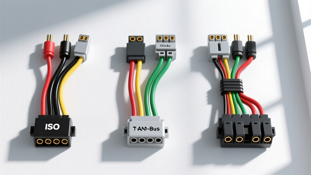
This guide compares the three primary car stereo wiring solutions—Standard ISO 10487 harnesses, Vehicle-Specific T-Harnesses, and CAN-Bus Integration Modules—providing the technical specifications, pinout configurations, and selection criteria required for professional-grade installations.
1. Standard ISO 10487 Harnesses: The Universal Baseline
The ISO 10487 standard defines the physical dimensions and pinouts for car radio connectors. While predominantly used in European vehicles and older universal aftermarket head units, understanding the ISO block structure is foundational for any car stereo wiring project.
ISO Block A (Power & Control)
Block A handles the power delivery and accessory signaling. The standard pinout utilizes specific DIN color codes:
- Pin 4 (Yellow): +12V Constant Battery Memory. Requires a direct connection to a fused battery source to retain head unit presets and clock data.
- Pin 5 (Blue/White): +12V Antenna Trigger / Amplifier Remote Turn-On. Outputs 300mA max; use a relay for high-current amplifiers.
- Pin 7 (Red): +12V Ignition/Switched Accessory.
- Pin 8 (Black): Chassis Ground. Must be secured to bare metal with a minimum 10mm contact area.
ISO Block B (Speaker Outputs)
Block B routes the amplified speaker-level signals. While ISO defines the pin positions (e.g., Pin 1 for Rear Right +, Pin 2 for Rear Right -), modern installers rely on the EIA/CEA-2002 standard color codes to prevent phase cancellation and cross-talk.
2. Vehicle-Specific T-Harnesses: Plug-and-Play Integration
T-Harnesses (or bypass harnesses) are designed to mate directly with the vehicle's factory radio plug on one end and the aftermarket head unit's ISO or 20-pin connector on the other. They eliminate the need to cut or splice the factory wiring loom.
When to Use a T-Harness
T-Harnesses are ideal for older vehicles (pre-2005) or base-model trim levels that do not utilize multiplexed data networks for radio control. They map standard 12V power, ground, illumination, and 8-channel speaker outputs directly to the EIA color codes.
Limitations and Failure Modes
The primary limitation of a standard T-Harness in modern vehicles is its inability to decode data commands. If a vehicle uses a CAN-bus signal to trigger the accessory power state (common in Chrysler, Ford, and VW platforms post-2008), a standard T-Harness will provide no 12V switched power to the red ignition wire. Furthermore, T-harnesses often use 20 AWG or 22 AWG wire to fit inside tight factory dash cavities. According to SAE J1128 standards for low-tension primary cable, 22 AWG wire is insufficient for modern head units with high-current internal amplifiers, leading to voltage drop and thermal degradation.
3. CAN-Bus Integration Modules: The Smart Interface
For late-model vehicles, a CAN-Bus integration module (such as those from PAC, Axxess, or iDatalink Maestro) is mandatory. These modules act as a gateway, translating the vehicle's high-speed digital data packets (CAN-High and CAN-Low) into standard 12V analog triggers and resistance-based SWC signals that the aftermarket stereo can understand.
Technical Capabilities of Smart Modules
- Data Decoding: Reads CAN-bus baud rates (typically 500 kbps) to generate a +12V accessory output when the ignition cylinder turns or the start button is pressed.
- Steering Wheel Controls (SWC): Converts factory resistor-ladder or digital SWC signals into the 3.3V logic required by aftermarket head units (Pioneer/Kenwood vs. Alpine/JVC protocols).
- Retained Accessory Power (RAP): Maintains head unit power until the driver's door is opened, mimicking factory logic.
- Backup Camera Integration: Triggers the reverse wire (typically Purple/White) only when the CAN-bus detects the transmission is in Reverse, bypassing the need to tap the high-voltage reverse light circuit.
For deep-dive programming and firmware flashing of these modules, referencing the iDatalink Maestro Support documentation is critical to ensure the correct vehicle firmware is loaded via USB before installation.
Car Stereo Wiring Harness Comparison Chart
| Feature | Standard ISO 10487 | Vehicle T-Harness (Analog) | CAN-Bus Integration Module |
|---|---|---|---|
| Primary Application | Universal / Pre-2000 Vehicles | 2000-2010 Base Models | 2010+ Multiplexed Networks |
| Wire Gauge (Typical) | 18 AWG | 20 AWG - 18 AWG | 16 AWG (Power) / 22 AWG (Data) |
| Accessory 12V Trigger | Hardwired Ignition | Hardwired Ignition | Software Decoded (CAN/LIN) |
| SWC Support | No | Resistor Ladder Only | Digital & Resistor Ladder |
| Vehicle Chime Retention | N/A | N/A | Yes (via internal speaker/CAN) |
| Installation Time | 45-60 Minutes | 15-20 Minutes | 60-90 Minutes (Flashing + Wiring) |
Wire Gauge Selection and Current Capacity
A common mistake in car stereo wiring is relying on the thin 20 AWG or 22 AWG wires found in cheap, universal harness adapters. Modern aftermarket head units with built-in 4x50W MOSFET amplifiers can draw upwards of 15 amps at peak transient volumes.
When selecting or modifying a harness, adhere to these AWG guidelines:
- 16 AWG Stranded Copper: Mandatory for the main +12V Constant (Yellow) and +12V Ground (Black) leads on high-power head units. This minimizes voltage drop and prevents the harness connector from melting under sustained thermal load.
- 18 AWG Stranded Copper: Acceptable for switched ignition (Red), illumination (Orange), and amplifier remote turn-on (Blue/White).
- Speaker Wire: Use a minimum of 16 AWG OFC (Oxygen-Free Copper) for speaker runs exceeding 6 feet to maintain damping factor and prevent high-frequency attenuation. For detailed vehicle-specific routing and factory wire color identification, the Crutchfield Vehicle Wiring Guide remains an industry-standard reference for factory pinouts.
Troubleshooting Common Car Stereo Wiring Failures
Even with the correct harness selected, integration issues can arise. Use this diagnostic tree to resolve common post-installation faults:
Symptom: Parasitic Battery Drain (Vehicle Won't Start After 24 Hours)
- Cause 1: CAN-Bus module failing to enter "sleep mode." The module continues polling the network because the head unit's CAN-High/CAN-Low lines are backfeeding voltage.
- Fix: Verify the CAN-bus module's sleep trigger wire is correctly configured. Ensure the aftermarket head unit is not outputting 5V logic on its data lines when powered off.
- Cause 2: Constant 12V (Yellow) and Switched 12V (Red) wired together at the head unit to "force" it to turn on.
- Fix: Separate the circuits. The head unit must see 0V on the Red wire to initiate its internal sleep sequence and shut down the CAN-bus interface.
Symptom: Alternator Whine / Ground Loop Noise
- Cause: The head unit ground is tied to a painted dash bracket, or the RCA grounds are referencing a different potential than the head unit chassis.
- Fix: Scrape away all paint and primer from the grounding point. Use a star washer and an M6 bolt torqued to 8-10 Nm. If using a T-Harness, run a dedicated 16 AWG ground wire directly from the head unit harness to a verified clean chassis point, bypassing the thin factory ground wire in the radio cavity.
Symptom: Steering Wheel Controls (SWC) Erratic or Unresponsive
- Cause: Incorrect SWC protocol selected in the head unit menu, or missing 3.3V pull-up resistor on the SWC data line.
- Fix: Most modern CAN-bus modules output a 3.3V logic signal. Ensure the head unit is set to the correct brand-specific protocol (e.g., Pioneer/JVC vs. Kenwood/Alpine). Use a multimeter to verify the SWC wire pulses between 0V and 3.3V when buttons are pressed. Do not connect factory 5V or 12V SWC lines directly to the head unit without a step-down resistor network.
Final Selection Verdict
Choosing the right car stereo wiring solution depends entirely on the vehicle's model year and network architecture. For classic cars and pre-2000 daily drivers, a robust 16 AWG ISO harness or analog T-Harness provides reliable power and speaker integration. However, for any vehicle manufactured after 2010 utilizing CAN-bus, LIN-bus, or MOST fiber-optic networks, investing in a premium CAN-Bus integration module is non-negotiable. It preserves vehicle safety features, retains OEM functionality, and provides the clean, regulated 12V triggers necessary for complex aftermarket audio systems.