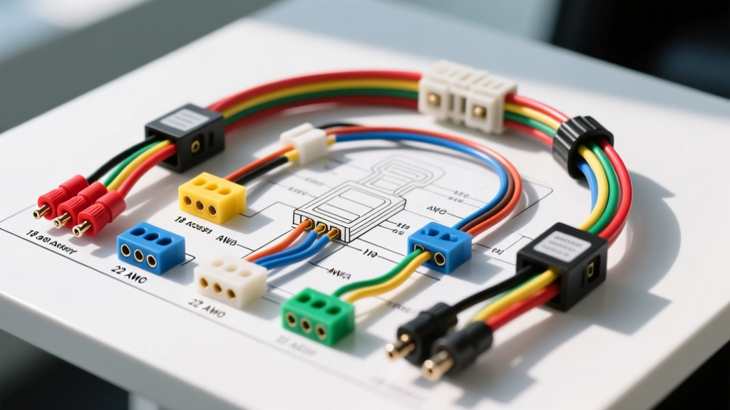
Introduction to the EIA/CEA RS-770 Wiring Standard
When installing an aftermarket head unit or integrating a new amplifier, understanding the universal car stereo wiring colour code is critical for a safe and functional installation. The Consumer Technology Association (CTA), formerly the Electronic Industries Alliance (EIA), established the RS-770 standard to unify aftermarket mobile electronics wiring. This standardization ensures that a Kenwood, Pioneer, Alpine, or Sony head unit will utilize the exact same wire colour functions, drastically reducing installation errors and electrical fires caused by miswired power circuits.
While the aftermarket standard is uniform, original equipment manufacturer (OEM) harnesses rarely follow these colours. Therefore, mastering the EIA/CEA standard allows installers to properly map aftermarket pigtail harnesses to vehicle-specific adapter harnesses (such as Metra or Axxess interfaces). This technical reference guide details the precise colour codes, American Wire Gauge (AWG) specifications, and ISO 10487 pinout mappings required for professional-grade mobile audio installations.
Primary Power, Ground, and Accessory Specifications
The main power bundle of a standard car stereo wiring colour code relies on specific insulation colours to designate constant memory, switched ignition, and chassis ground. According to SAE J1128 standards for low-tension primary automotive cable, these wires must withstand under-hood and under-dash temperature variations, though standard head unit pigtails typically use PVC-insulated 18 AWG stranded copper.
| Wire Colour | Function | Standard AWG | Max Amperage / Fuse |
|---|---|---|---|
| Yellow | Constant 12V+ (Battery / Memory) | 18 AWG | 15A (Direct to Battery) |
| Red | Switched 12V+ (Accessory / Ignition) | 18 AWG | 10A (Fuse Panel) |
| Black | Chassis Ground | 18 AWG | 15A (Clean Metal Point) |
| Orange | Illumination (12V+ when headlights on) | 22 AWG | 3A |
| Orange/White | Dimmer Control (Variable Voltage) | 22 AWG | 3A |
| Blue | Power Antenna Trigger (12V+ Radio On) | 22 AWG | 5A |
| Blue/White | Amplifier Turn-On / Remote (12V+) | 22 AWG | 5A (Up to 10A w/ Relay) |
Critical Power Routing Notes
The Yellow (Constant) and Red (Switched) wires are frequently swapped by novice installers. If the Red wire is connected to a constant 12V source and the Yellow to a switched source, the head unit will turn on and off with the key, but the internal volatile memory will be severed every time the ignition cycles. This results in the loss of radio presets, EQ settings, and clock configurations. Always verify the vehicle's fuse box with a digital multimeter (DMM) to confirm which circuit maintains voltage with the key removed.
Standard Speaker Wiring Colour Code Matrix
The speaker output section of the EIA/CEA standard utilizes a base colour for the positive (+) terminal and a matching colour with a black stripe (or black tracer) for the negative (-) terminal. Standard head unit harnesses utilize 22 AWG or 20 AWG wire for speaker outputs, which is sufficient for the typical 14W to 22W RMS per channel output of standard Class AB or Class FD internal amplifiers.
| Speaker Location | Positive (+) Wire | Negative (-) Wire |
|---|---|---|
| Front Left | White | White with Black Stripe |
| Front Right | Gray | Gray with Black Stripe |
| Rear Left | Green | Green with Black Stripe |
| Rear Right | Purple | Purple with Black Stripe |
Expert Insight: When wiring passive crossovers or component speakers, maintaining absolute phase (polarity) is crucial. Reversing the positive and negative wires on a single speaker will result in acoustic phase cancellation, severely degrading mid-bass response and collapsing the stereo soundstage. Use a 9V battery to 'pop' the speaker cone outward to verify polarity before soldering or crimping connections.
ISO 10487 Connector Pinout Mapping
While the wire colours dictate the function, the physical connection at the back of the head unit is governed by the ISO 10487 standard. This standard defines two primary blocks: Block A (Power and Control) and Block B (Speaker Outputs). Understanding the pinout is essential when building custom harnesses or diagnosing factory radio plugs that mimic ISO configurations.
Block A: Power and Control (8-Pin)
- Pin 1: Mute Control / Telephone Mute (Usually unused in modern aftermarket)
- Pin 2: Mute / Reverse Camera Trigger (Varies by manufacturer)
- Pin 3: Speedpulse / Reverse Gear Signal
- Pin 4: Constant 12V+ (Yellow Wire)
- Pin 5: Power Antenna / Amp Remote Turn-On (Blue or Blue/White Wire)
- Pin 6: Illumination / Dimmer (Orange Wire)
- Pin 7: Switched 12V+ (Red Wire)
- Pin 8: Chassis Ground (Black Wire)
Block B: Speaker Outputs (8-Pin)
- Pin 1: Rear Left + (Green)
- Pin 2: Rear Left - (Green/Black)
- Pin 3: Front Right + (Gray)
- Pin 4: Front Right - (Gray/Black)
- Pin 5: Front Left + (White)
- Pin 6: Front Left - (White/Black)
- Pin 7: Rear Right + (Purple)
- Pin 8: Rear Right - (Purple/Black)
OEM vs. Aftermarket: The CAN-Bus Complication
The traditional car stereo wiring colour code assumes an analog 12V switched ignition signal (Red wire). However, modern vehicles (roughly 2008 and newer) utilizing CAN-bus, GMLAN, or LIN-bus data networks no longer provide a high-current analog accessory wire. Instead, the factory radio is 'woken up' via a digital data packet sent over a twisted pair of data wires.
If you attempt to tap into a CAN-bus line using the standard Red accessory wire, you will not only fail to power the radio, but you risk shorting the data bus, which can trigger catastrophic module failures across the vehicle's network. In these applications, the standard EIA/CEA colour code must be interfaced through a data retention module (such as those from PAC or iDatalink Maestro). These modules read the vehicle's digital data wake signal and output a standard analog 12V Red wire to trigger the aftermarket head unit, preserving the universal wiring standard on the radio side of the harness.
High-Current Head Unit Upgrades: Breaking the 18 AWG Rule
The standard 18 AWG power wire is rated for roughly 16 amps in a chassis wiring scenario. For a standard 14W x 4 RMS head unit, the total current draw rarely exceeds 8 amps, making 18 AWG perfectly adequate. However, premium aftermarket units featuring built-in Class FD or high-power Class AB amplifiers (e.g., 45W x 4 RMS or 50W x 4 RMS) can draw upwards of 20 to 25 amps at peak volume.
According to resources like the Crutchfield vehicle wiring database and mobile electronics installation guidelines, running 25 amps through a standard 18 AWG pigtail will cause severe voltage drop, wire heating, and premature failure of the head unit's internal PCB traces. For high-current head units, professional installers will cut the Yellow, Red, and Black wires at the harness plug and solder them to a dedicated 14 AWG or 12 AWG power harness wired directly to the battery and a dedicated chassis ground point, bypassing the factory fuse panel entirely.
Multimeter Verification and Troubleshooting Decision Tree
Never rely solely on a vehicle's factory wire colours, as OEMs frequently change colour codes mid-production year or across different trim levels. Always verify with a Digital Multimeter (DMM) before making connections.
Symptom: Head Unit Powers On, But Loses Memory When Key is Removed
- Cause: The Yellow (Constant) and Red (Switched) wires are reversed.
- Fix: Use a DMM to find the vehicle wire that holds 12.6V with the key OFF. Connect this to the aftermarket Yellow wire. Find the wire that shows 0V with key OFF and 12.6V with key ON. Connect this to the aftermarket Red wire.
Symptom: Alternator Whine in Speaker Outputs
- Cause: Ground loop caused by using the vehicle's factory speaker negative wires as a ground path, or a poor Black wire chassis ground.
- Fix: Ensure the Black ground wire is terminated to bare, unpainted chassis metal using a ring terminal and a self-tapping screw or bolt. Verify that speaker negatives (the black-striped wires) are isolated from the chassis and run all the way back to the head unit's internal amplifier ground plane.
Symptom: Amplifier Turns On Immediately, Draining Battery
- Cause: The Blue/White (Amp Remote) wire is incorrectly spliced to the Yellow (Constant) wire instead of the proper head unit remote output.
- Fix: Isolate the Blue/White wire and ensure it is only receiving 12V when the head unit is physically powered on. Use a relay if the head unit's Blue/White circuit cannot handle the combined current draw of multiple amplifiers and DSPs.